20
1. 8 7 7. 8 7 7. 2 269 BLACKBOX.COM
NEED HELP?
LEAVE THE TECH TO US
LIVE 24/7
TECHNICAL
SUPPORT
1.877.877.2269
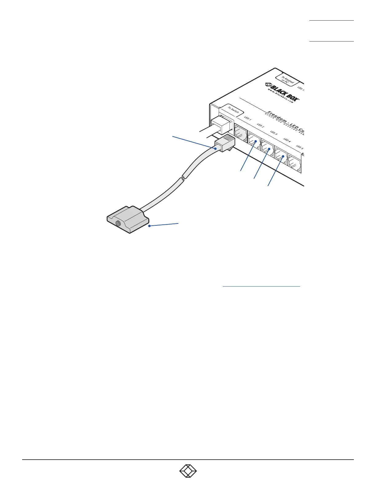
2. Link each LED indicator to a port on the Freedom LED Monitor module -
ports 1 to 4 are most commonly used.
See Figure 3-8.
3. You need to tell the Freedom LED Monitor which LED indicator to illuminate (and in which color) for each channel. To do this con-
nect your computer to the Freedom II switch via a network connection (see 4.1.1.1 To temporarily connect a computer to the net-
work port) and use the Glide and Switch application. Please see the section 4.4 Configuring LED indicators.
4. Apply power to the switch.
LED indicator with
3 metre lead
Port 2
Port 3
Port 4
Insert the lead for
the first indicator
into port 1
Each indicator has a self adhesive Velcro
tab to assist with mounting on your
video displays.
Figure 3-8. Linking LED indicators to the Freedom LED Monitor module.
Note: The KV0004A-LED kit
includes four LED indicator
assemblies. Up to ten can be
connected and additional LED
indicators can be ordered using
the part number: KV0004A-
XTRA-LED.
 Loading...