M ULTI-FUNCTION READER MF4100 INSTALLATION GUIDE
D OCUMENT 1295 REV 01
PRINTED N OVEMBER 3 , 2 0 0 9 1-7
The MF4100 can be powered using the +12 Volt wall mount power supply (included), or Power
Over Ethernet (POE) switch. The power supply requires a dedicated 110 VAC outlet. POE
provides power through the network cable, and reduces cable clutter. A CAT-5 cable must be
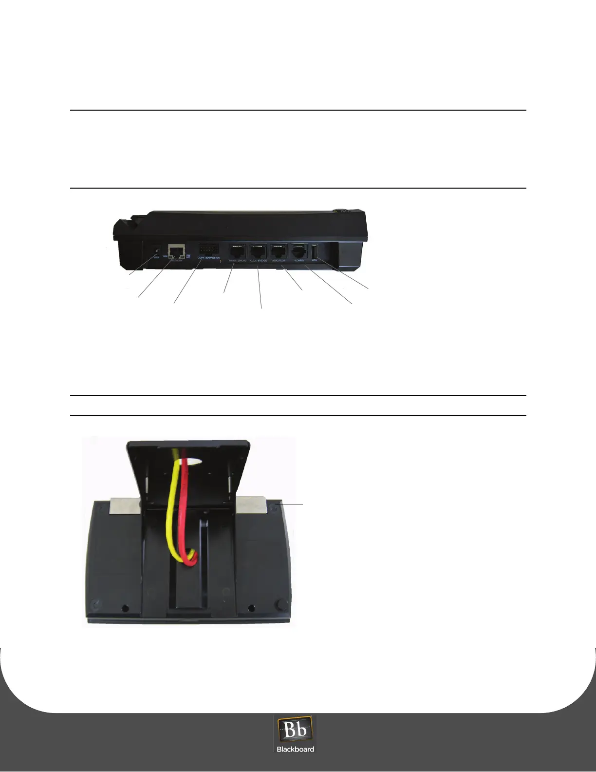
connected between the POE switch to the RJ-45 connector on the MF4100 labeled Network,
see the diagram below. When providing power with POE, the maximum LAN cable length
must not exceed 100 meters.
Figure 1-11 MF4100 Cable Ports
7 Place the security plate onto the MF4100, and then route the cables through the plate opening.
Note the orientation of the VESA bracket to the security plate.
Figure 1-12 Attended Wall Mount VESA Bracket Orientation
8 Place the MF4100 assembly on the pivot plate, and then secure using four M4 x 6mm machine screws
provided in the hardware kit.
Power Supply
Network/POE
Copy
Print/LWCFG
AUX1/Bridge
AUX2/LCM
Config
USB
Expansion