W ALL MOUNT INSTALLATION
PRINTED N OVEMBER 3, 2009
1-8
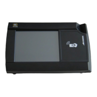
Figure 1-13 Reader Secured to Pivot Plate - Attended Wall Mount
9 Position the pivot plate to the desired angle, and then tighten the 2 locking screws (1/8” pin hex driver).
Unattended Wall Mount Installation
1 Find a location on a single gang box to mount the MF4100.
Ensure there is enough clearance for the operator to access the touchscreen and swipe cards.
2 Remove the two base extensions by removing the 4 screws (1/8” pin hex driver).
See: VESA Bracket Assembly Details (Page: 4).
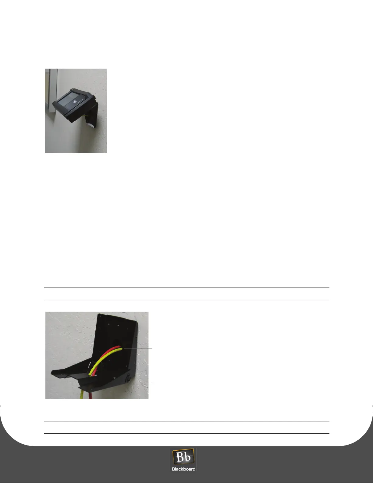
3 Route the required cables through the VESA bracket cable hole, and then the pivot bracket hole.
Note the orientation of the VESA bracket to the wall.
Figure 1-14 VESA Bracket - Unattended Wall Mount
Note: The pivot plate attaches to the bottom of the MF4100 reader.