M ULTI-FUNCTION READER MF4100 INSTALLATION GUIDE
D OCUMENT 1295 REV 01
PRINTED N OVEMBER 3 , 2 0 0 9 1-9
4 Attach the mounting base to the gang box using the two #6-32 pin hex screws provided in the
hardware kit.
5 Install cables to the connectors of the MF4100.
See: MF4100 Cable Ports (Page: 7).
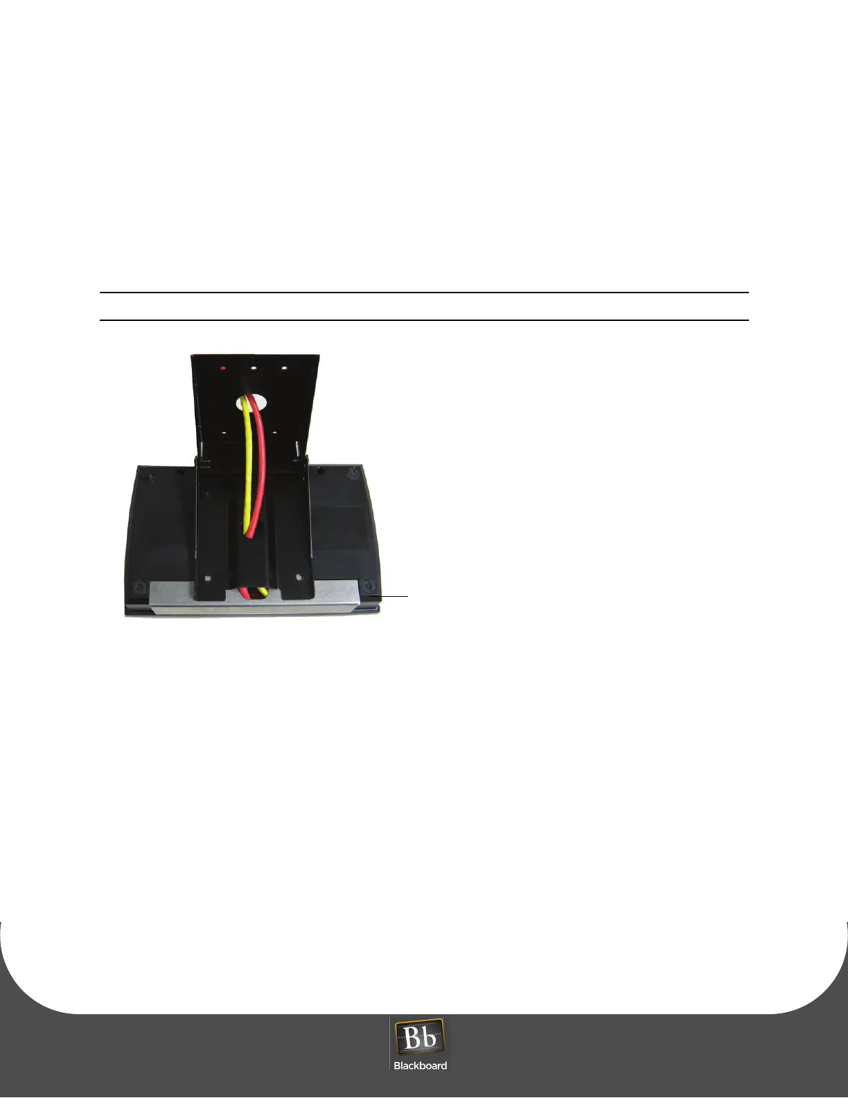
6 Place the security plate onto the MF4100, and then route the cables through the plate opening.
Note the orientation of the VESA bracket to the security plate.
Figure 1-15 Unattended Wall Mount VESA Bracket Orientation
7 Place the MF4100 assembly on the pivot plate, and then secure using four M4 x 6mm machine screws
provided in the hardware kit.
8 Position the pivot plate to the desired angle, and then tighten the 2 locking screws (1/8” pin hex driver).