Using the ATEM 1 M/E Broadcast Panel
41
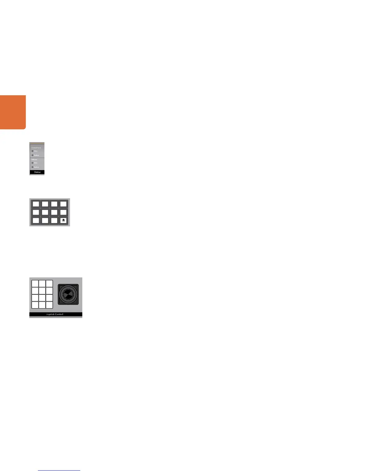
System Status
The status lights provide feedback on the power supplies connected to the broadcast panel and the
switcher. Not all ATEM switcher models have redundant power supplies so sometimes you will only see a
single light illuminated for the power status of the switcher.
However if your switcher model has redundant power and you have connected two power supplies to
the switcher and the control panel, then all the lights should be on. In this situation where you are using
redundant power supplies, any light that turns off could indicate a power supply is faulty, and this should
be checked.
System Control
The twelve menu buttons, the display window, the four knobs and the four soft buttons under the knobs
together are called the system control. The 4 line display is used to identify the operation of the soft buttons
and knobs.
The system control is context sensitive and allows you to adjust parameters for the current operation. For
example if you enable KEY 1 in your next transition, the system control allows you to adjust the parameters
of KEY 1. The system control is also used for configuring other parts of the switcher.
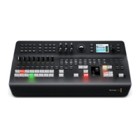
Menu Buttons
The matrix of menu buttons are organized into a multi level tree structure of pages that are very easy to
navigate. To assist in rapid navigation all menu pages have a HOME button at the bottom right and most
operations only require navigating down one level.
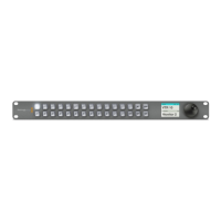
Joystick and Numeric Keypad
The Number Pad is used to enter numerical data. For example, when setting the transition rate of a
transition, the number pad can be used to enter a numerical value for the transition duration. When entering
data using the number pad, the soft buttons below each parameter are used to apply the entered data to
that parameter.
The Joystick is a 3-axis joystick that is used to size and position keys, DVEs and other elements.