31
Programming
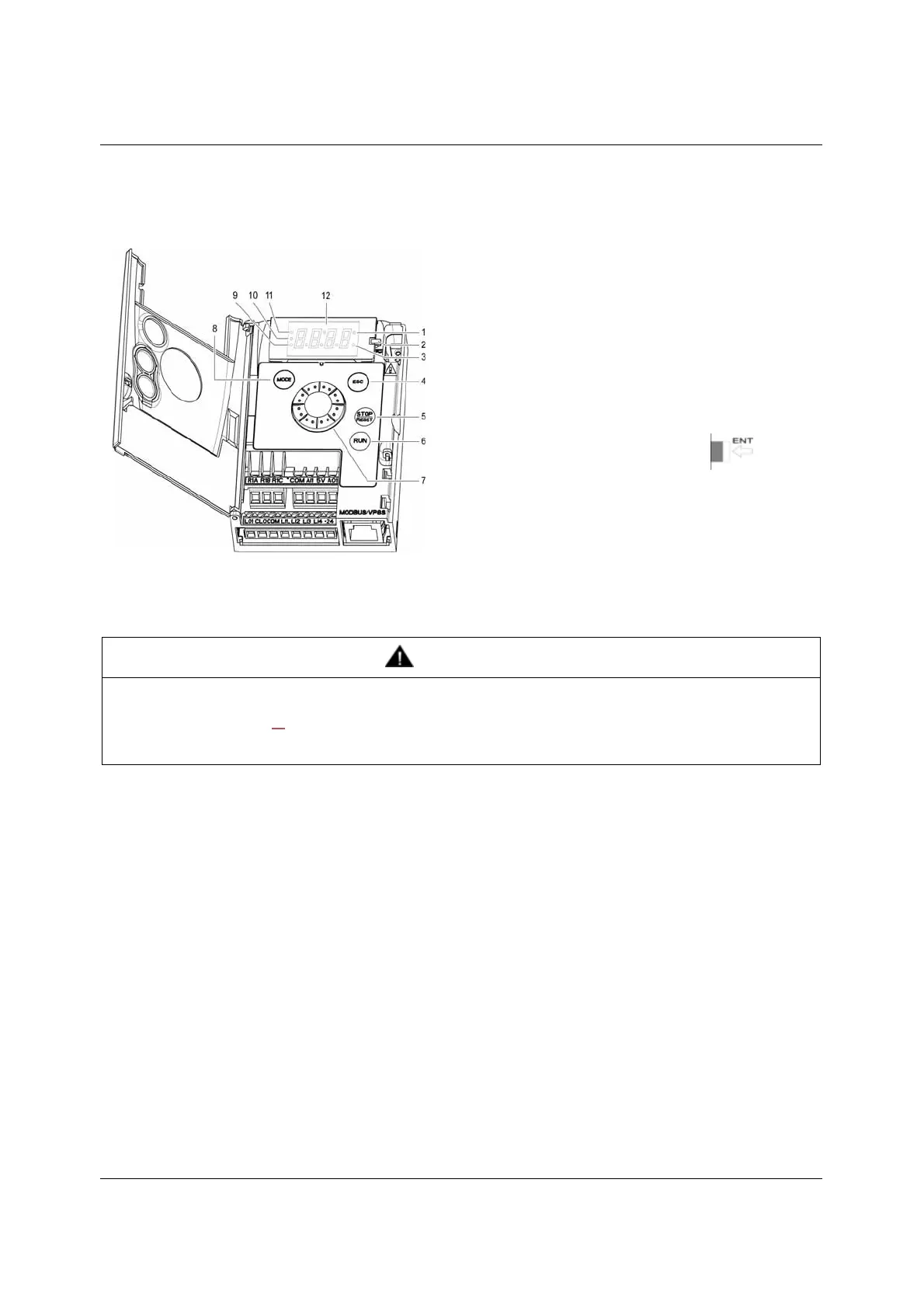
HMI description
Functions of the display and keys
(a) If illuminated, indicates that a value is displayed, for example,
(b)When changing a value the Configuration mode LED and the value LED are on steady.
(c) If illuminated, indicates that a unit is displayed, for example, AMP is displayed for "Amps"
1. Value LED (a) (b).
2. Charge LED
3. Unit LED (c)
4. ESC button: Exits a menu or parameter, or aborts the displayed
value to return to the previous value in the memory.
5. STOP button: stops the motor (could be hidden by door if function
disabled). Important: See instructions for "RUN/STOP" cover
removal.
6. RUN button: Starts running if the function is configured (could be
hidden by door if function disabled).
7. Jog dial
- Acts as a potentiometer in local mode.
- For navigation when turned clockwise or counterclockwise
- and selection / validation when pushed.
This action is represented by this symbol
8. MODE button
Switches between the control/programming modes. The MODE
button is only accessible with the HMI door open.
9. CONFIGURATION mode LED (b)
10. MONITORING mode LED
11. REFERENCE mode LED
12. Four "7-segment" displays
WARNING
LOSS OF CONTROL
The stop buttons on ER12 drive and on the remote keypad display can be programmed to not have priority. To retain stop key priority,
set Stop key priority PSt page 60
to YES. Do not set PSt to nO unless exterior stopping method(s) exist.
Failure to follow these instructions can result in death, serious injury, or equipment damage.
5 is displayed for "0.5"0.