ELECTRIC CONVECTION OVENS 6 INSTALLATION
UTILITY CONNECTION
ELECTRICAL CONNECTION - ALL UNITS EXCEPT MARK V XCEL
Wiring diagrams are located in the control compartment and on the back of the oven. Ovens are supplied for operation in
several voltage choices, single or three phase grounded circuits. The electric motor, indicator lights and related switches are
connected the one power source supplied to the oven.
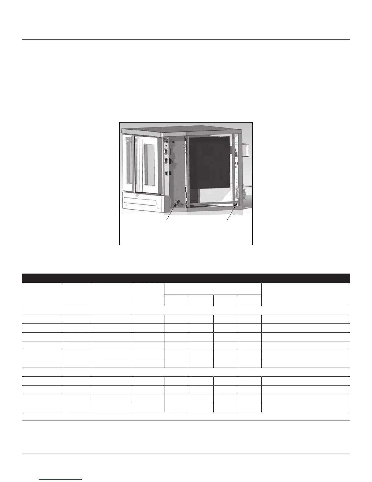
The supply conduit enters through the rear of the oven and electrical block secured to the perforated panel at the back of
the control compartment.
THE BLODGETT OVEN COMPANY CANNOT ASSUME RESPONSIBILITY FOR LOSS OR DAMAGE SUFFERED AS A
RESULT OF IMPROPER INSTALLATION.
Connect wires to
terminal block
Run supply line through
the knock-out
Figure 5
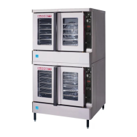
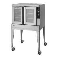
FULL SIZE OVENS
KW
HZ
VOLTAGE
PHASE
MAX LOAD (AMPS ELECTRICAL
CONNECTION
(MINIMUM SIZE)*
L1 L2 L2 N
U.S. and Canadian installations
11.0 60 208 1 51 — 51 — 6 AWG
11.0 60 208 3 31 29 29 — 8 AWG
11.0 60 220-240 1 44 — 44 — 6 AWG
11.0 60 220-240 3 26 24 24 — 8 AWG
11.0 60 440 3 15 14 14 — 12 AWG
11.0 60 480 3 14 13 13 — 12 AWG
General Export installations
11.0 50 220-240 1 48 — — 48 Size per local code
11.0 50 220/380 3 18 15 15 3 Size per local code
11.0 50 240/415 3 18 14 14 4 Size per local code
11.0 50 230/400 3 18 15 15 3 Size per local code
NOTE: *Electric connection wiring is sized for 90ºC copper wire at 125% of rated input.