Task Procedures Illustrations
194
AT6020
a
e
g
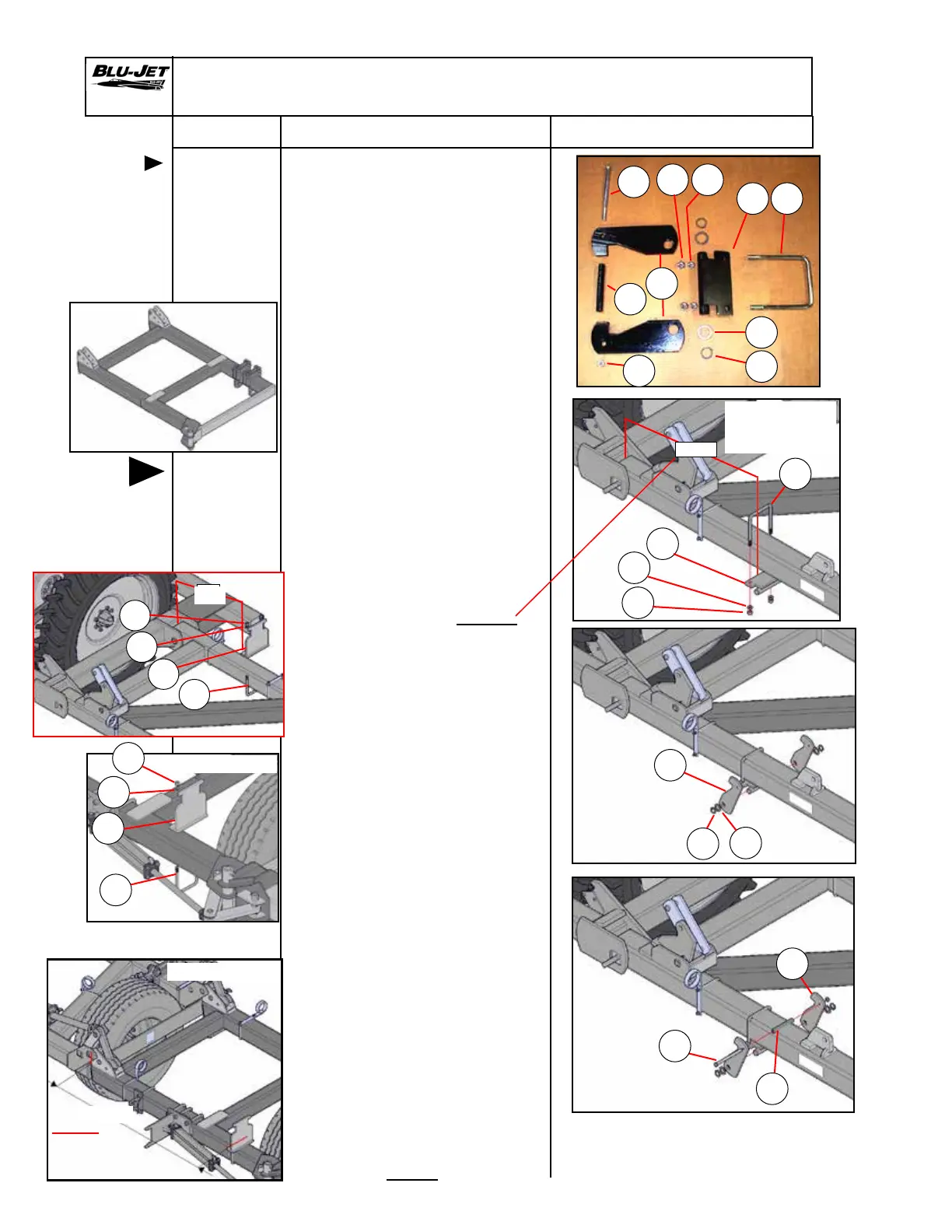
Installation
of secondary
wing latch
hydraulic
gauge wheel
secondary
wing
Secondary Wing Latch With Hydraulic Gauge Wheel
Consult
row
spacing
page for
placement
of latch
c
j
d
c
j
d
h
b
i
b
i
g
a
e
f
f
43-1/2”
35”
k
m
n
l
m
n
k
l
35”
1. a. AM4566 2 Wing latch
pivot, secondary
wing
b. AM4567 2 Pipe spacer
c. AM4568 4 Secondary wing
lock plate
d. AP2711 4 Snap ring, 1-1/4”
external, heavy
duty
e. BP3038 2 Nut, hex, 5/8”-11,
grade 2, plated
f. BP3039 2 Lock washer
5/8”, plated
gf. BP3354 2 U-bolt 5/8”-11
x 6” x 7-3/4”,
plated
hg.BP3179 2 Hex cap screw,
1/2”-13 x 8”,
grade 5, plated
ih. BP3244 2 Nut, hex lock,
1/2”-13
ji. BP3249 4 Machinery
bushing, 1-7/8”
OD x 1-1/4” ID,
14 Ga.
2. Place (a) (AM4566) wing latch
pivot on bottom of rear
primary wing tube 43-1/2”
from hinge to back of latch
Install (g) (BP3354) 5/8” x 6”
x 7-3/4” u-bolt into pivot
bracket. Place (f) (BP3039)
5/8”lock washers and
(e) (BP3038) 5/8” hex nuts
on u-bolt. Tighten hex nuts
enough so the pivot bracket
will still slide on tube.
3. Install (c) (AM4568) secondary
wing lock plates on both sides
of pivot bracket. Secure with
(j) (BP3249) 1-7/8” OD x 1-1/4” ID
machinery bushing and (d)
(AP2711) 1-1/4” snap ring heavy
duty.
4. Raise both wing lock plates
and install (h) (BP3179) 1/2”
x 8” hex cap screw through
plate (b) (AM4567) pipe spacer
and second plate. Secure with
(i) (BP3244) 1/2” hex lock nut.
5. Check placement before
tightening 5/8” hex nuts on
u-bolt.
6. Attach (k) (AM6151) wing rest
with (l) (BP 3354) 5/8” x 6” x 7-3/4”
u-bolt, (m) (BP3039) 5/8” lock
washers and (n) (BP3038) 5/8”
hex nuts 68-1/2” from hinge
weldment to front edge of
Tractor side
68-1/2”
68-1/2”
Tractor side
AM6169 LH
AM6169 LH
Wing stop position the
same for AM6168 R
73-1/2”
20” even row
spacing
38-1/2”
20” even row
spacing
h
 Loading...