LD6 MAIN BOOM INSTALLATION
10
The LD6 main boom assembly, Fig. 1, is shipped with
the retaining pins and bolts installed. It will be
necessary to remove the pins and bolts as the main
boom is being assembled to the main frame. The main
boom should be attached to the main frame as follows:
(1) Remove the ¾” x 10 ½” plated bolt (Item 15 in
the main frame assembly) and ¾” self-locking hex nut
(Item 16 in the main frame assembly) from the yoke of
the swing shaft. Position the base end of the main boom
(Item 1) between the mounting ears (use two men or
overhead hoist) and secure by re-inserting the ¾” x
10 ½” plated bolt through the yoke ear and boom as
shown in Fig. 2. The bolt should be seated (or
locked) in the locking ring on the outside mounting ear
of the yoke to prevent bolt from turning during
operation. Fasten the bolt in place with the ¾”
self-locking hex nut, tightening for fit but not
sufficiently to warp the yoke mounting ears.
Fig. 2
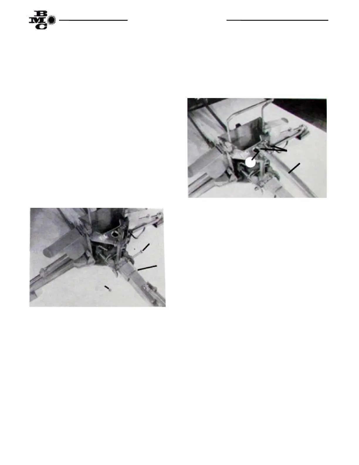
(2) Mount the base end of the main boom cylinder
(Item 2) with flat top end of the swing shaft between
the ears of the cylinder clevis. Secure the boom cylinder
with a ¾” x 2 ¾” cylinder pin (Item 3) and two each
1/8” x 1” cotter pin (Item 4) as show in Fig. 3.
Fig. 3
(3) Install one each of the SAE 6 O-Ring to JIC 6 Flare
straight adapter fittings (Item 1 in box parts, Page 5) in
both ports of the crowd cylinder.
16
15
1
3
2
4