MD8 DIPPER ARM INSTALLATION
19
7
8
9
The MD8 dipper arm (crowd) assembly, Fig. 1, is
shipped assembled with the retaining pin and bolt
installed in the dipper arm. It will be necessary to
remove the locking pin and crowd cylinder bolt
before the dipper can be attached to the main boom.
Attach the dipper arm to the main boom in the
following manner:
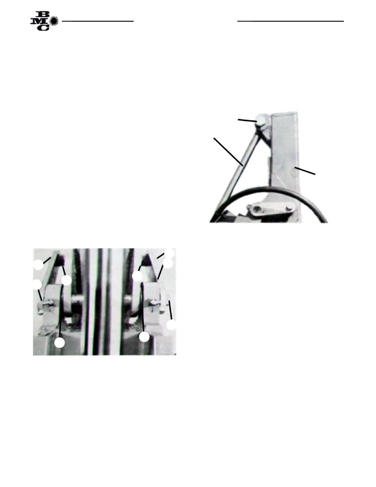
(1) Remove the locking pin (Item 2) from the dipper
arm (Item 1). Using overhead hoist, raise the main
boom until the dipper arm can be placed between the
swivel lugs on the top end of the boom as shown in Fig.
2. Place two each spacers (Item 6, one on each side of
the dipper) between the dipper and the boom. Insert
the locking pin (Item 2) through the boom swivel lugs,
spacers and dipper arm. Secure the locking pin in place
by using the locking pin plate (Item 3), ½” x 1 ½” bolt
(Item 4) and a ½” lockwasher (Item 5). Insert a ½”
I.D. x 1” O.D. x 1 ¼” spacer (Item 7) between the arm
on the locking pin and the dipper arm, securing with a
½” x 2 ¼” bolt (Item 8) and ½” lockwasher (Item 5).
Using the other ½” I.D. x 1” O.D. x 1 ¼” spacer (Item
7), insert between the dipper arm and the locking pin
plate securing with a ½” x 2 ¼” bolt and ½”
lockwasher.
Fig. 2
(2) Raise rod end of crowd cylinder and position
pin-eye on end of cylinder rod between anchor lugs on
the dipper arm as shown in Fig. 3. Secure the cylinder
with a 1” x 4 ½” bolt (Item 9) and 1” self-locking hex nut
(Item 10). The bolt should be inserted from the left side
and the head of the bolt locked in the locking ring
located on the side of the anchor lug.
Fig. 3
(3) Install one each of the SAE 6 O-Ring to JIC 6 Flare
Straight adapter fitting (Item 1 in box parts) into each of
the bucket cylinder ports.
crowd cyl.
rod
2
6
6
4
3
7
8
dipper
arm