LD6 MAIN FRAME INSTALLATION
7
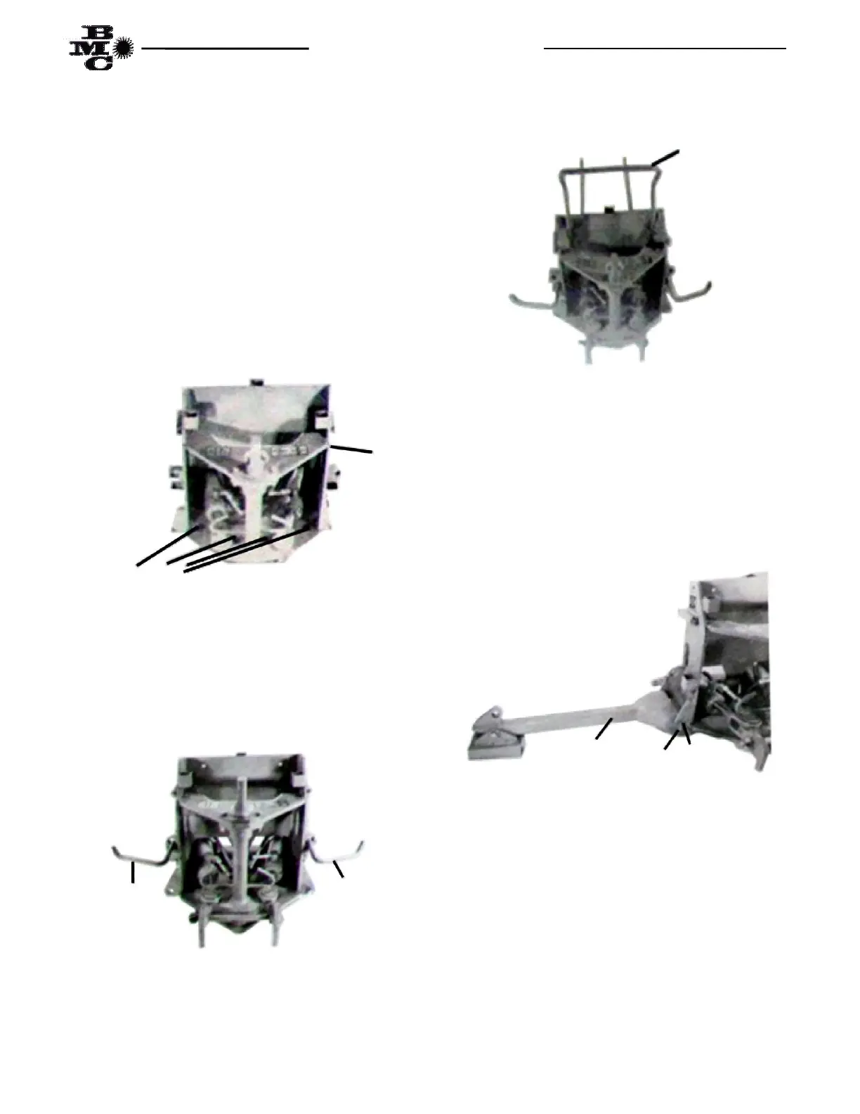
The LD6 main frame assembly, Fig 1, is shipped with
some of the retaining pins and bolts installed. It will be
necessary to remove the pins as the different parts are
assembled on the main frame. The main frame should
be installed on the mounting frame plate as follows:
(1) Position the Backhoe Mainframe (item 1) over the
Mounting plate on the Mounting Frame. Maneuver the
mainframe until the eight holes in the mainframe align
with the eight (8) holes in the mounting plate. Secure
the mainframe with eight (8) each 5/8” x 2” machine
bolts, lockwashers and hex nuts supplied in the
mounting frame kit. Torque the bolts and nuts per
Table 1, Page 39.
Fig. 2
(2) Install the left step (Item 3) in the step mounting
receptacle located on the left side of the Backhoe main
frame with orientation of the step as shown in Fig. 3.
(3) Repeat step two to install the right step (Item 2).
Fig. 3
(4) Install the grab bar (Item 4) in the grab bar
mounting receptacle located on the inside of the side
plates and just above the top plate. Secure the grab bar
with two (2) 3/16” x 1 ½” cotter pins (Item 11) as
shown in Fig. 4.
Fig. 4
(5) Attach the left stabilizer arm (Item 5) between
the stabilizer mounting lugs, located on the left side of
the mainframe near lower edge, securing the arm to the
mainframe with one (1) each stabilizer pin (Item 6) and
two (2) each 3/16” x 1 ½” cotter pins as shown in Fig.
5.
(6) Repeat step 5 for the right side stabilizer arm.
Fig. 5
(7) Attach base end of (1) each stabilizer cylinder
(Item 9) to left side of main frame cylinder anchor lug,
located in the center and just above the base end of the
stabilizer arm, using one each cylinder pin (Item 10)
and two each 3/16” x 1 ½” cotter pins (Item 11) as
shown in Fig. 6.
3
Bolts Machine 5/8” x 2”
1
2
4
5
6 11