Retrofit/Installation kit No. 65 90 0 025 169 Issue date: 10.2001
Installation instructions No. 01 29 0 030 090
A
A1
A2
A3
A4
A5
A6
A7
A8
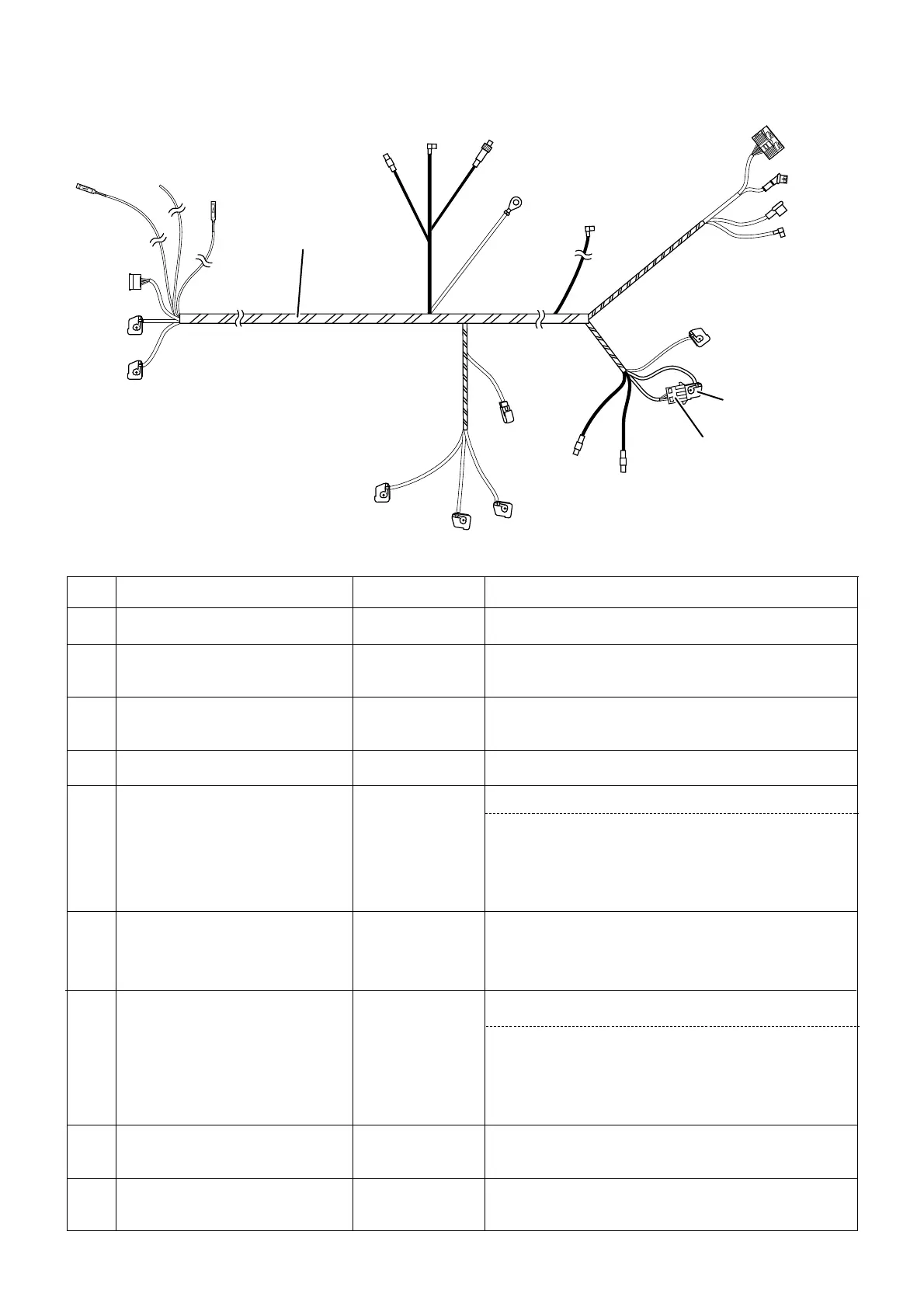
On-board monitor wiring harness
Blue 12-pin
socket casing
White 12-pin
socket casing
Black 17-pin plug casing
socket contact, terminal RS
free cable end
socket contact, terminal TAA
Coaxial socket casing
Coaxial socket casing
-
To blue 12-pin plug casing on the on-board monitor (9)
To white 12-pin plug casing on the on-board monitor (9)
To radio connection plug X18126
at black 54-pole light module connector X10117 in PIN38;
if PIN38 assigned, cut off socket contact and provide
free cable end with 2-way insulation-piercing connector
at power supply cable, cable colour blue/yellow, PIN38 of
the black 54-pole socket housing X10117 at the light
module
provide with 2-way insulation-piercing connector at
power supply cable, cable colour brown/red, PIN1 of the
blue 26-pole socket housing X10114 at the instrument
cluster
at white 18-pole instrument cluster connector X10113 in
PIN3.
if PIN3 assigned, cut off socket contact and provide free
cable end with 2-way insulation-piercing connector at
power supply cable, cable colour black/white, PIN3 of the
white 18-pole socket housing X10113 at the instrument
cluster
To the coaxial plug casing on the aerial amplifier above
the left wheel arch
To be laid to the installation site of the left TV amplifier
above the left wheel arch and tied back
Item Description
Cable colour Connection site in the car
-
-
-
-
blue/yellow
brown/red
black/white
black
black