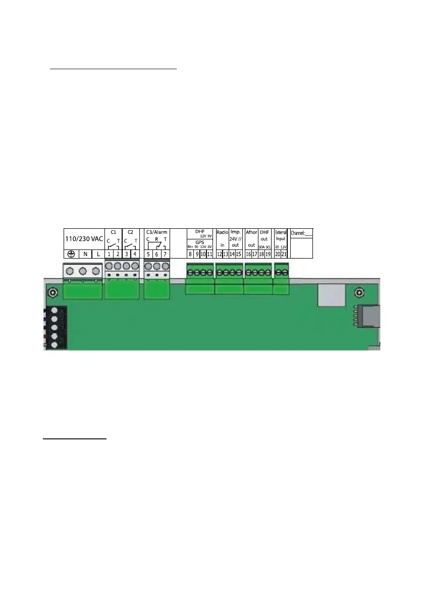
8.2 Electrical connections
Connect the cables (mains power supply, impulse line or AFNOR output
and radio synchronisation input, depending on the model) to the
corresponding terminal strips as shown in the figure below.
(*) See page 18, the “Time outputs” menu to set this output (Pulse minute,
½ minute, second 24V or power TBT 24VDC 0,5A).
(**) depending on the SIGMA model.
RACK version: The mains power supply, impulse line and AFNOR output
and radio synchronisation input terminal strips are directly accessible at the
rear of the Rack slide-in unit.
25
Attach the wires to each
other, near the terminal
strips.
3C tiu criC
See the limit
characteristics of
these circuits on
page 28.
la nretxE tupni
tu ptuo FHD
es ro nm ½ ,etu niM )*( -
95-2RS ro ,V42 dnoc
FCD ro I-F
tupni oi dar
tupni SPG
tuptuo ronfA
2C tiu criC
(**) 110 to
230VAC or
24VDC
or
36/72VDC
1C tiu criC
 Loading...