BOGE Operating instructions trinity Page 5
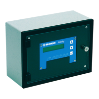
General 1.3 Components / Range of application
Electrical connections
13 connecting terminals in tension spring technology – can be operated from
above:
1. Two alternatively useable inputs for the two supply voltages ‚
– 230 V 50/60 Hz (1, 2)
– 24 V 50/60 Hz (4, 5)
2. Support terminal for PE conductor (3).
3. Analog input for one pressure transmitter 4...20 mA in two-wire technique
(+ = 6, input = 7).
4. Three short-circuit resistant transistor outputs 20 mA for couple relay
(coil connection A1 = + and A2 = –)
– Compressor 1: + = 8 and – = 9.
– Compressor 2: + = 10 and – = 11.
– Compressor 3: + = 12 and – = 13.
10-pole plug for transmission of software and parameters (ISP interface) –
may only be used in connection with 230 V supply, because otherwise a rec-
tifier would be bridged
→ damage to microprocessor!
Software
1. Two of the needed pressure switch points (highest and lowest) must be
set. The others are automatically calculated.
2. The number of compressors is to be set to 2/3.
3. For same size compressors: adjustable cyclic priority change – every
1...250 hours possible - in the case of each periodic change – if the actual
pressure value is not above the switch off pressure values – all compres-
sors first get output releases.
4. For different compressor use: week-switching time mode can be parame-
terized (set cyclic priority change time via Code 832 to ’0 h’)
→ – 26 switch
points (A...Z) can be used.
All possible priority combinations including total-output lock can be set.
5. Integrated clock with operation reserve (>10 h) in case of power failure.
6. Pressure display combined with display of actual output compressors pos-
sible – example: 10.0 bar C1 C_C3.
7. Pressure display combined with display of actual compressor priority
sequence possible – example: 10.0 bar C3
→ C1 → C2. If (during timer
operation) the compressor is shut off, 'C1...C3: _' or 'C1+C2: _' is dis-
played. In case of an error message, 'C1..C3: l' or 'C1+C2: l' is displayed
– this message may not disappear before the next priority change (can be
eliminated at once by manipulation during timer operation).
8. Pressure display combined with display of actual cycle rest time – in h with
three decimal places possible (number procedure can be observed, if not
in timer operation) – Example: 10.0 bar 1.234 h.
9. Pressure display combined with display of actual time (day-no hh:mm)
possible – example: 10.0 bar 2 08:23h.
10. Display of set lowest and highest pressure switch point possible – exam-
ple: P<10.50> 9.50 bar.
11. Display of exact time (day-no. hh:mm:ss) possible – example: 1..7
→ 2
08:23:45 h.