4 Installation of Hardware
The supplied modem is connected
− to the frequency inverter (plant side) or
− the PC (PC side).
Attention! •
The modem may only be connected to an analog telephone line. If
connected to a digital telephone line, (e.g. ISDN), the modem will be
damaged. For information on the connection, refer to the modem
operating instructions.
4.1 Modem on Plant Side
Warning! • Before electrical installation work, disconnect the frequency inverter
from power supply and take appropriate precautions to make sure it
is not re-energized unintentionally.
• Carry out the mechanical and electrical installation according to the
installation instructions given in the operating instructions. Comply
with the safety instructions provided there.
Danger! • When the frequency inverter is disconnected from power supply, the
mains, DC-link voltage and motor terminals may still be live for some
time. Wait for some minutes until the DC link capacitors have
discharged before starting to work at the unit.
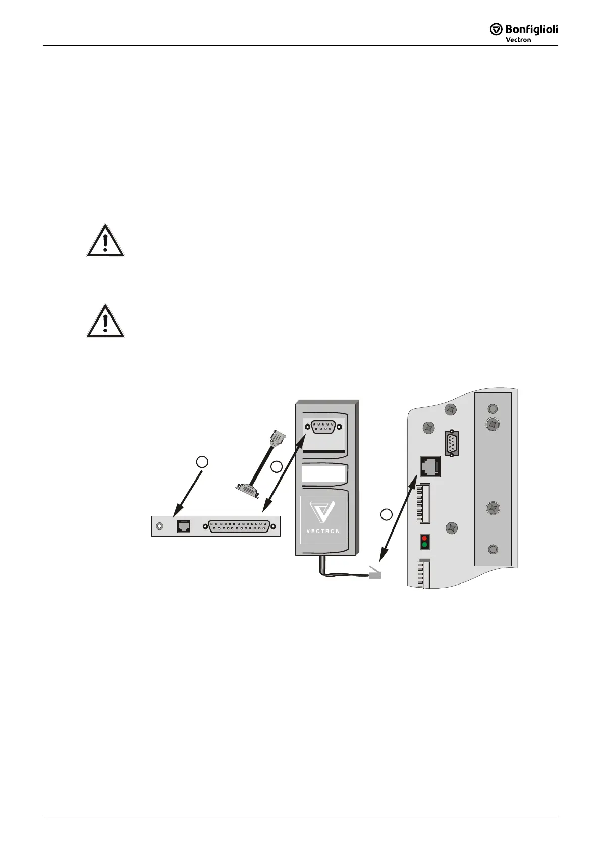
4.1.1 Connecting the Modem to Devices of the VCB Series:
1
1
211
8
H1
Schnittst.-Umsetz.
RS232-KP100
3
H2
1
X215
2
1. Connect the supplied interface converter RS232-KP100 to the socket X215 of the
frequency inverter.
2. Connect the modem to the interface converter RS232-KP100 using the serial cable.
• To do this, plug the 25-pin Sub-D connector in the 25-pin Sub-D socket at the
modem.
• Then, plug the 9-pin Sub-D connector at the other end of the cable in the 9-pin
Sub-D socket at the interface converter RS232-KP100.
3. For the connection of the modem
− to the telecommunication system and
− power supply,
please refer to the modem operating instructions.
611/07

 Loading...


