Page
66
3BE390580NI – 07/07
BONNET CIDELCEM GRANDE CUISINE
Siége social:
Rue des Frères Lumière - Z.I Mitry Compans
77292 MITRY MORY Cedex
4. INSTALLATION: CONNECTIONS
4.1 ELECTRIC CONNECTION
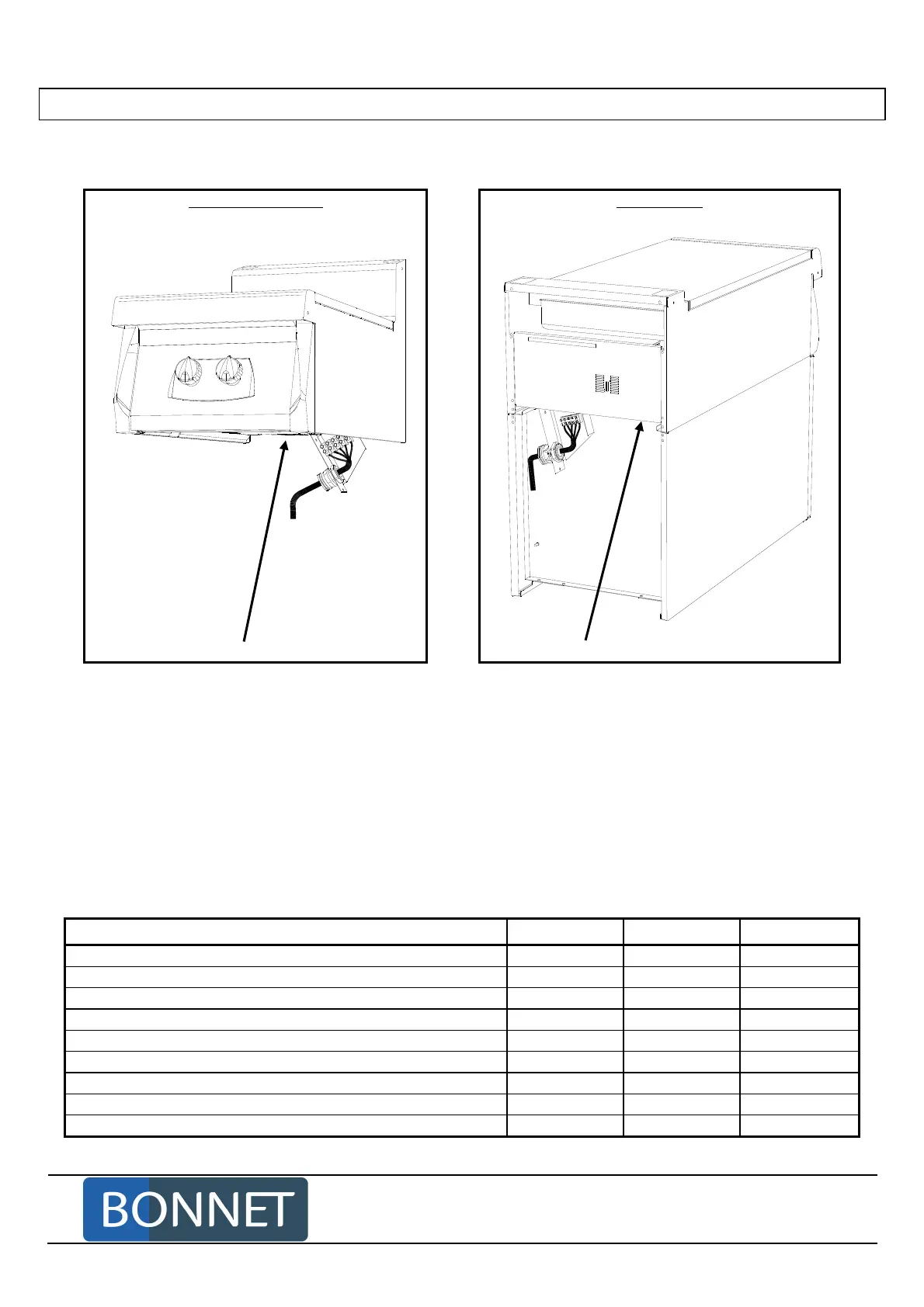
Ready-to-install top Cooking unit
Location of the equipotentiality terminal Location of the equipotentiality terminal
Electric connection is carried out from the back of the appliance, whatever the model is.
- Unscrew the fixation screw of the terminal strip support lug.
- Tilt towards the left.
- Introduce the cable through the gland.
- Tighten the gland.
- Connect the wires.
- Put the lug back in place.
- Connect the equipotential link to the terminal foreseen for the purpose.
• Only use supply cables of the H07 RN-F type with a section depending on equipment and the supply
voltage (see the chapter "Technical Characteristics"):
D
ESIGNATION
(700 and 900 ranges) 230 V a.c. 230 V 3 a.c. 400 V 3N a.c.
Ready-to-install bain marie 400
3 x 2.5 mm
2
4 x 2.5 mm
2
5 x 2.5 mm
2
Ready-to-install fries warmer 400
3 x 2.5 mm
2
4 x 2.5 mm
2
5 x 2.5 mm
2
Bain marie on neutral cupboard 400
3 x 2.5 mm
2
4 x 2.5 mm
2
5 x 2.5 mm
2
Bain marie on heating cupboard 400
3 x 2.5 mm
2
4 x 2.5 mm
2
5 x 2.5 mm
2
Neutral fries warmer on heating cupboard 400
3 x 2.5 mm
2
4 x 2.5 mm
2
5 x 2.5 mm
2
Infra red fries warmer on neutral cupboard 400
3 x 2.5 mm
2
4 x 2.5 mm
2
5 x 2.5 mm
2
Infra red fries warmer on heating cupboard 400
3 x 2.5 mm
2
4 x 2.5 mm
2
5 x 2.5 mm
2
Neutral top on heating cupboard 400
3 x 2.5 mm
2
4 x 2.5 mm
2
5 x 2.5 mm
2
Neutral top on heating cupboard 800
3 x 2.5 mm
2
4 x 2.5 mm
2
5 x 2.5 mm
2