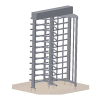
THT-100
34
Boon Edam Inc.
402 McKinney Parkway Version: Rev A6 10/28//2011
Tel. 910-814-3800 fax 910-814-3899 Issue: THT-100-IMM-USA
5.10 Configuration
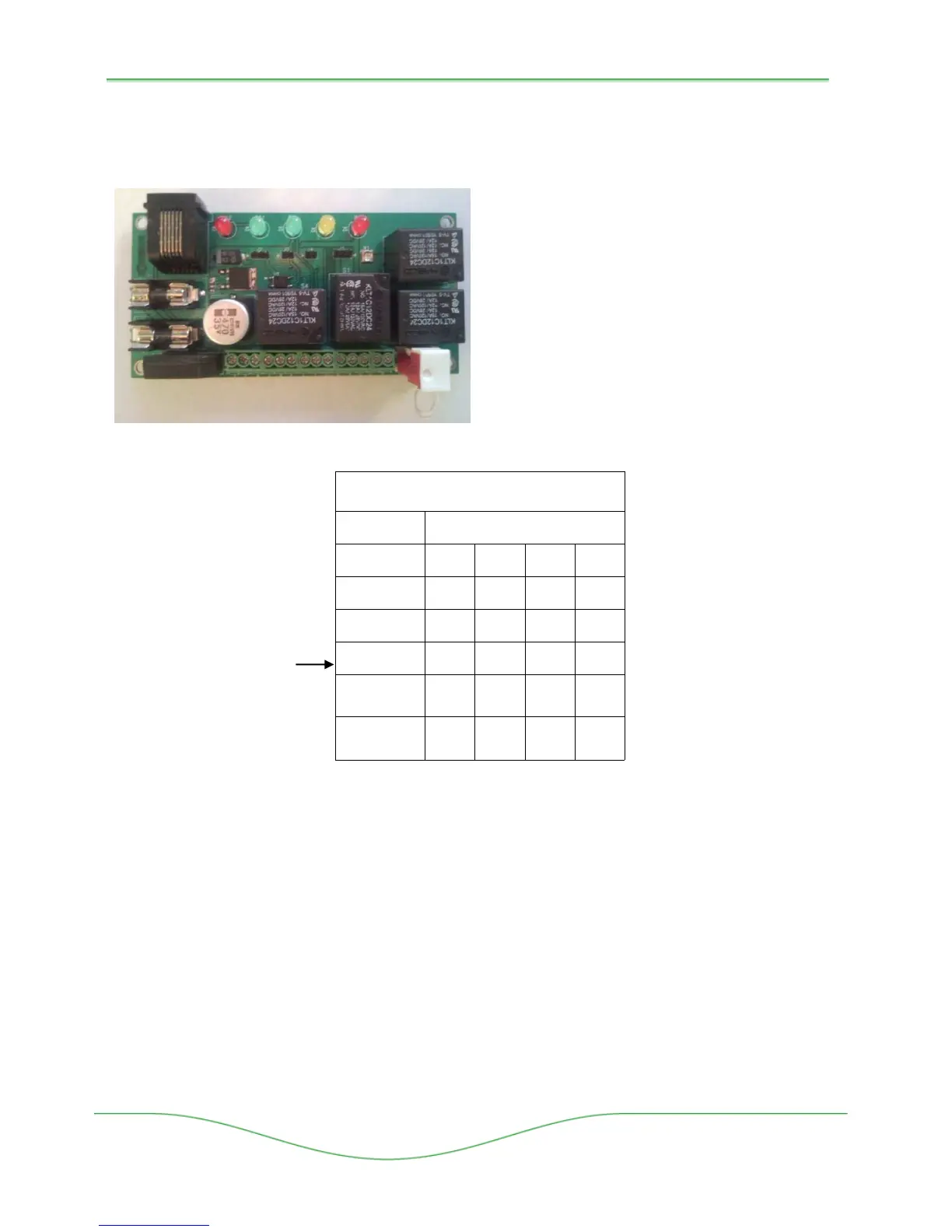
A series of jumpers are pre-configured on the main control board(s) specific to each
configuration (i.e., Fail Safe/Fail Lock). Each board is configured for a single direction of travel:
Figure 5-20: MCB Detail
FUNCTION
J2 J3 J4 J7
PINS TO JUMP ON JUMPER:
NO PULSE OR
TIME OUT CIRCUIT
TIMEOUT CIRCUIT
ONLY
PULSE CIRCUIT
ONLY
PULSE AND TIME
OUT CIRCUITS
2-3 2-3 - -
2-3 1-2
-
-
- 2-3
1-2
1-2
- 1-2
1-2 1-2
SERIAL PORT
INTERFACE
W/OUT TIMEOUT
- 2-3
-
-
SERIAL PORT
INTERFACE
W/TIMEOUT
- 1-2
-
-
JUMPER CONFIGURATIONS
Figure 5-21: Jumper Configuration Chart
Configuration Definitions:
• Time Out Relay – Provides a time out duration after a valid access is granted. The
setting of potiometer R1 determines the holding duration of this relay. After the hold time
expires the unit will return to its standby state.
• Pulse Relay – When the Access Control System sends an access grant signal to the
MCB, a one-shot pulse will automatically generate internally; regardless of how long the
ACS input signal is held.
• Serial Port Interface – Allows the MCB to react to wet voltages (3-25vdc) in leu of dry
contact inputs on the X1 terminals. Options for signal transmission TD or SD (Transmit
Data), DTR (Data Terminal Ready), RTS (Request to Send Data).
Start-up
Board Layout
• Jumpers - J2, J3, J4, J7 (reference Jumper
Configuration Chart for specific settings).
• R1 – Potentiometer to adjust time out
duration.
• Staus LEDs
D11 – Fault Condition Indicator
D12 – Normal Operation Indicator
D1 – Lock Activated
D2 – Pulse Trigger
D3 – Pulse Relay
• Fail Safe/Fail Lock Jumper
• Fuses – 1.5 Amp
• Serial Port Interface
Port
Factory Default Settings
 Loading...