Do you have a question about the BOON EDAM THT-100 and is the answer not in the manual?
Provides an overview of the manual's purpose and scope for the THT-100.
States Boon Edam's ownership of manual information and third-party disclosure restrictions.
Outlines product design compliance and maintenance responsibilities for warranty.
Explains Boon Edam's right to improve products without notice, potentially causing minor differences.
Details crucial safety precautions for installing and maintaining the THT-100 turnstile.
Covers essential safety rules for operating the THT-100, including supervision of minors.
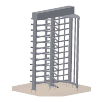
Provides a general overview of the THT-100 Full Height Turnstile, its components, and capacity.
Presents available configurations for the THT-100's shield assembly, including standard and optional types.
Illustrates various barrier assembly options for the THT-100, noting material variations.
Describes the ceiling plate's material and its fixed position between the top channel and barrier.
Details the different rotor arm assembly options available for the THT-100 turnstile.
Explains optional infill cover pieces for the THT-100 rotor arms.
Shows standard and optional top channel cover designs for the THT-100.
Describes the THT-100's control box, MCB, and solenoids in the top channel assembly.
Details the three possible speed control system options for the THT-100.
Lists typical THT-100 configurations and explains Fail Lock and Fail Safe functions.
Explains how the THT-100 integrates with access control systems via authorization signals.
Highlights security features like Restposition, Barrier Unit, and Shield Assembly in the THT-100.
Details optional features like Rotation Detection Switch, Home Position Switch, and Traffic Lights.
Describes optional boxes for mounting card readers and routing wires for access control.
Explains the optional system to reduce bounce and slow down rotor arms.
Describes an optional mechanical lock to prevent the unit from turning.
Describes optional heating elements for top channel mechanisms in cold climates.
Explains THT-100 configuration for fire alarm systems, including power failure overrides.
Discusses optional keyswitches for selecting operational modes like Card Read In/Free In.
Provides essential steps and warnings before starting the THT-100 installation.
Details typical packaging for THT-100 units and notes variations for tandem/special orders.
Lists required tools and manpower for a typical THT-100 installation.
Provides torque values for bolt connections during installation.
Explains the recommended anchor techniques using 3/8" minimum anchor bolts.
Illustrates typical anchor locations for Counter Clockwise and Clockwise entry installations.
Guides on marking the center line, center point, and layout dimensions for floor mounting.
Details the installation of the base plate, shield, and barrier assemblies.
Describes placing and greasing the bottom bearing and covering it with the flange.
Explains how to place and tighten rotor arm assemblies onto the bottom flange pin block.
Details securing the upper flange blocks to the rotor arm posts.
Explains the installation of optional infill pieces for specific THT-100 models.
Describes assembly of specific optional rotor arm types with snap-in infill pieces.
Guides on positioning the top channel for proper resting position using alignment features.
Details connecting the ceiling plate and top channel to the shield and barrier posts.
Explains how to fit and secure the standard top channel cover.
Details requirements for mains power supply and conduit hole locations.
Shows typical cable plug layouts and descriptions for the Main Control Box.
Explains how access control system connections are terminated to terminal strips in the main control box.
Describes pre-configured jumpers on the main control board for various travel directions.
Provides a chart for jumper settings on the MCB for different functions.
Defines Time Out Relay, Pulse Relay, and Serial Port Interface functions.
Outlines the general pre-configuration and start-up procedure for the THT-100.
Explains how to adjust the time out relay potentiometer for delay duration.
Details the procedure for adjusting the optional speed control dampening system.
Presents an exploded view diagram of the THT-100 and a parts description table.
Emphasizes the need for daily safety inspections by the owner/manager.
Lists specific checks for daily safety inspections of the THT-100 unit.
Provides guidance on weekly and semi-annual maintenance tasks for the THT-100.
Recommends weekly cleaning for proper operation and optimal function of the equipment.
Advises on planned maintenance inspections by authorized agents.
Offers guidance for diagnosing and resolving common issues with the THT-100.
Details troubleshooting steps for the control box and main control board.
Provides troubleshooting tips for the top channel mechanism, including solenoids and dampening.
Covers troubleshooting for rotor arm issues, such as loose arms or incorrect home position.
Lists specifications for the Main Control Board and Main Transformer.
Details power supply, duty cycle, temperature range, and response time for solenoids.
Provides specifications for the barrier type, application, capacity, finish, and rotor arms.
Introduces the appendix section containing supporting information.
Lists spare parts with part numbers, descriptions, and comments for the THT-100.
Contains electrical schematic diagrams for the THT-100 control system.
Illustrates the THT-100 tandem unit with two sets of rotor arms and mechanisms.
Shows an illustration of the TASTG curved shield tandem unit.
Displays an illustration of the THT-100TL tandem unit.
Notes that specific project information can be added in this chapter.
| Type | Turnstile |
|---|---|
| Material | Stainless steel |
| Capacity | Up to 30 people per minute |
| Power Supply | 230 VAC |
| Safety Features | Emergency stop button, safety sensors |