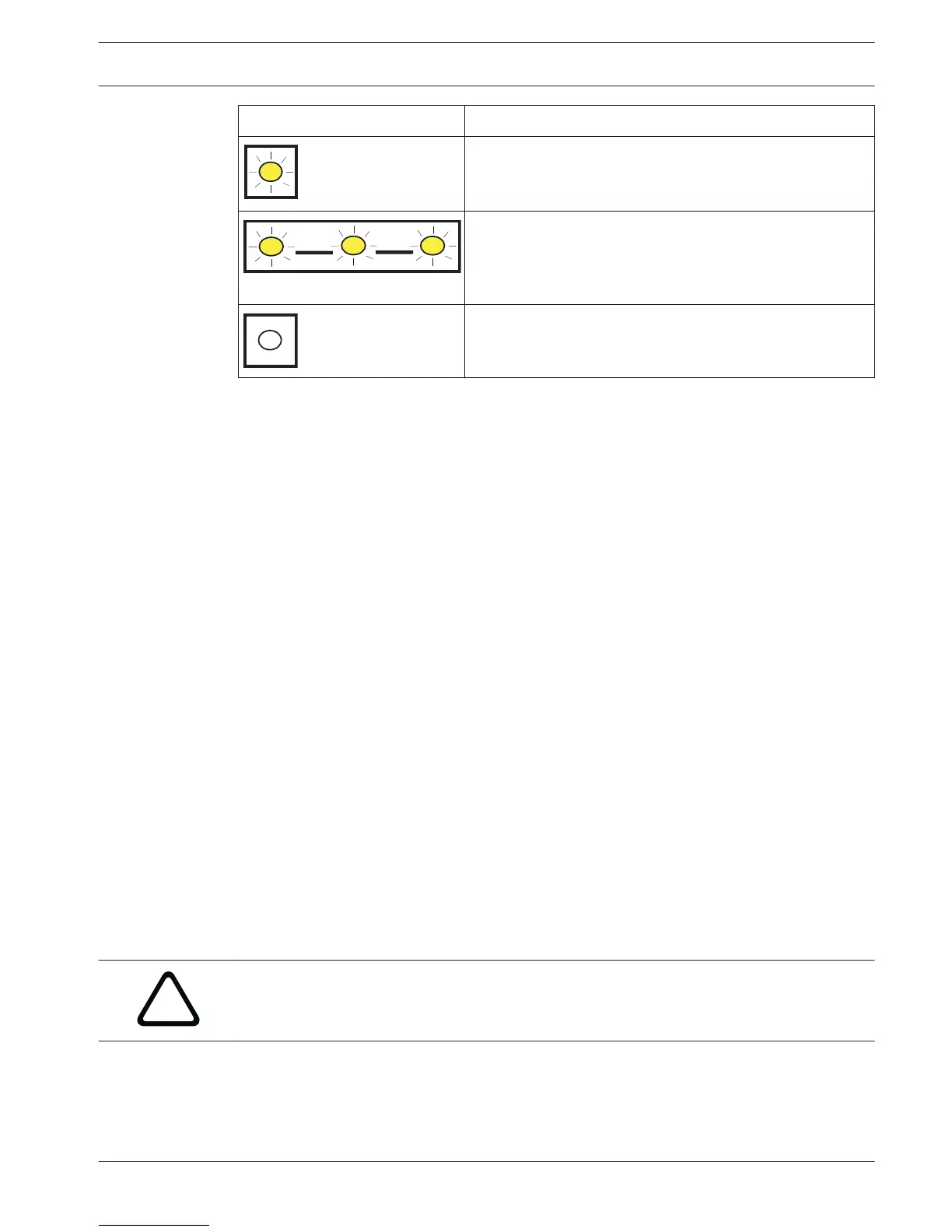
Flash pattern Function
On Steady
Plugged into an Ethernet network.
Flashing
Communication in progress.
Off
Unplugged from an Ethernet network, or the Ethernet
network is not available.
Table 8.2: LINK LED descriptions
Conettix Plug-in Cellular Communicators
Cellular plug-in communicators provide communication between the control panel and central
monitoring stations or RPS using a cellular network. The module also sends and receives SMS
messages for personal notification or system configuration.
The control panel supports one Connetix plug-in cellular module (directly plugged into the
control panel or plugged into a B450).
Connect a module using the plug-in module connector or using a B450 Conettix Plug-in
Communicator Interface (refer to the Conettix Plug-in Communicator Interface (B450)
Installation and Operation Guide and B450 Conettix Plug-in Communicator Interface, page 47).
This section includes basic installation instructions. For detailed instructions, refer to the
corresponding Conettix plug-in module document listed in Related documentation, page 11.
Supervision
The control panel supervises a plug-in cellular communicator when the control panel uses the
module in any of the four route groups as part of either the primary route or the backup route,
and the control panel uses the module to route any personal notifications. Supervision
ensures reliable operation between the module and the control panel.
If supervised and the module does not respond to control panel supervision polls, then a
system fault message shows on the keypads. The control panel sends a corresponding report
to the central station.
Installation and module wiring (B44x)
Ensure that there is enough power for the module and other powered devices you want
connected to the system.
Refer to On-board outputs, page 58.
Caution!
Remove all power (AC and battery) before making any connections. Failure to do so might
result in personal injury and/or equipment damage.
Install the module
The module plugs into a connector and is held in place with a plug-in module retention clip.
The module handle and support on top of the module hold the unit during installation.
8.2
8.2.1
8.2.2
Control Panel IP communications | en 41
Bosch Security Systems, Inc. Installation and System Reference Guide 2015.07 | 12 | F.01U.287.180
 Loading...


