Document number BST-BME280-HS006-00 | May 2018 Bosch Sensortec
© Bosch Sensortec GmbH reserves all rights even in the event of industrial property rights. We reserve all rights of disposal such as copying and passing on to third
parties. BOSCH and the symbol are registered trademarks of Robert Bosch GmbH, Germany.
Note: Specifications within this document are subject to change without notice.
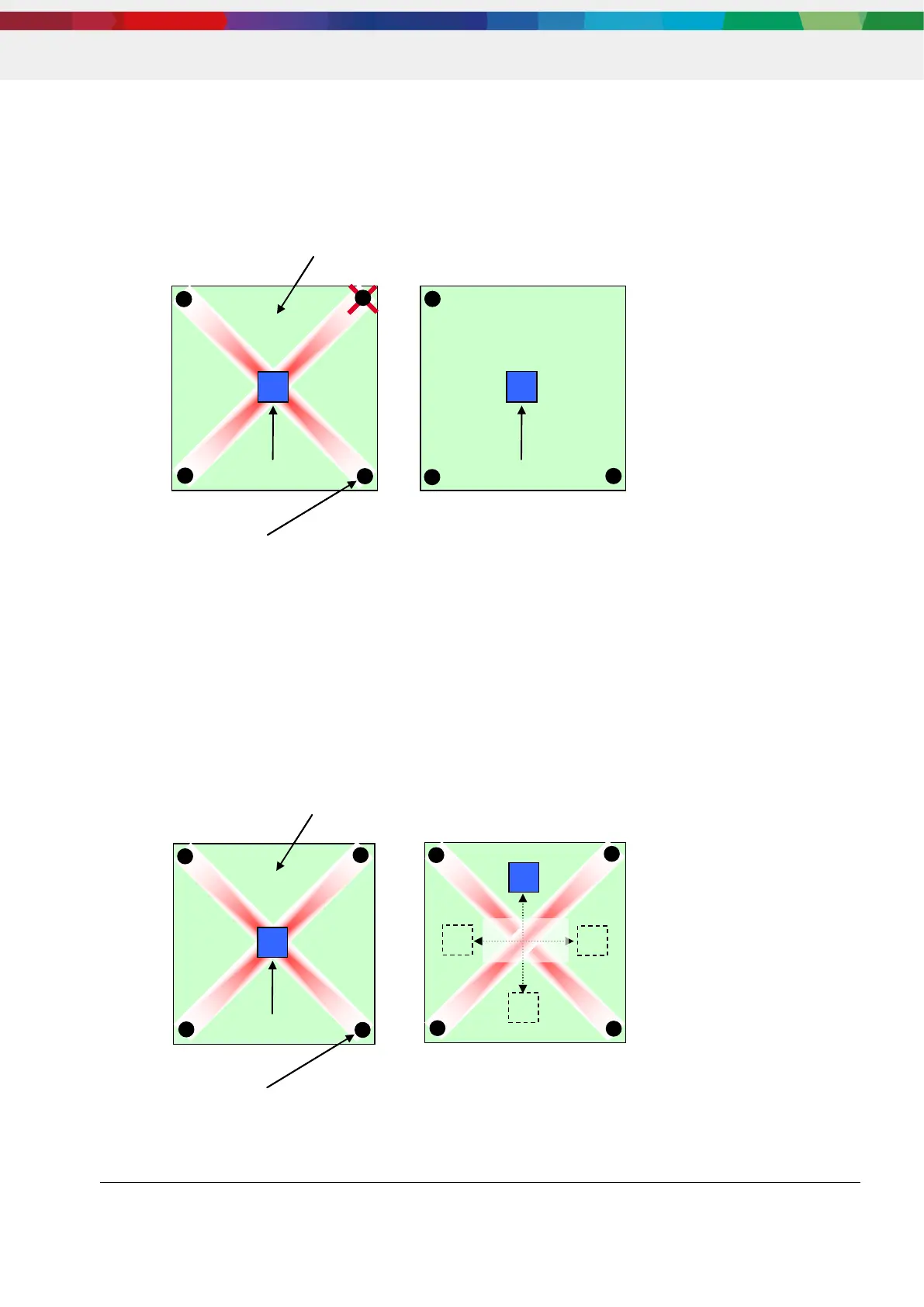
5.10. Redundant PCB anchor points
It is recommended to unscrew or remove any redundant PCB anchor points. In theory, an ideal flat plane
is determined by 3 anchor points, exclusively. Any further anchor point will over-determine the ideal flat
plane criteria. If these redundant anchor points are out of plane position (which means not 100% exact in
plane position) the ideal flat criteria is infringed, resulting in mechanical stress.
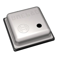
5.11. Mechanical stress maximum on the PCB
It is recommended to keep a reasonable distance from any mechanical stress maximum, when placing
the sensor device. Mechanical stress can be induced for example by redundant anchor points, as
described in 7.1.7.
The below given example will show a stress maximum in the center of the diagonal crossover of the 4
anchor points. It is good manufacturing praxis to always avoid or reduce the mechanical stress by
optimizing the PCB design first, then to place the sensor in an appropriate low stress area.