@
BOSCH
Flexible Automation
Simulation
Description Stage 4 Chapter 1
Definition,
function:
CC
lOOM
User Manual
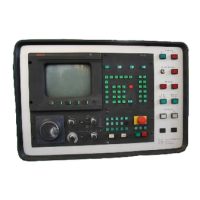
Simulation provides graphic support before execution. It offers the possibility of checking and
optimizing the part program. The individual work steps
of
thE?
part program are simulated in true-
to-~fe
manner. The user sees the tool traverse movements
with
the current speed (GO,G1). The
speed can be varied via potentiometers.
The programmed contour becomes visible step
by step from the workpiece which is displayed in
the correct position (zero shift, actual values), Note that the contour is produced from the traverse
paths
of
the tool canter-point path. It is not a direct contour description. The control checks the
program for operability, collision risks and technological boundary conditions. The function is
available
in
group operating mode AUTOMATIC. The movements
of
the tool canter point
are
visualized
in
a 2 112-0 display. The axes of the selected working plane are represented in a 2-D
image, whilst
the third axis perpendicular
to
the working plane
is
represented on a vertical "scale"
displayed next to the 2-D image.
Simulation always starts with
the current machine position; traversing
of
the machine is not
possible.
The simulation speed can be switched over at any time between the programmed speed (status:
NORMAL) and immediate
display (without interpolation).
1-2

 Loading...


