11
4.12 LED indicators
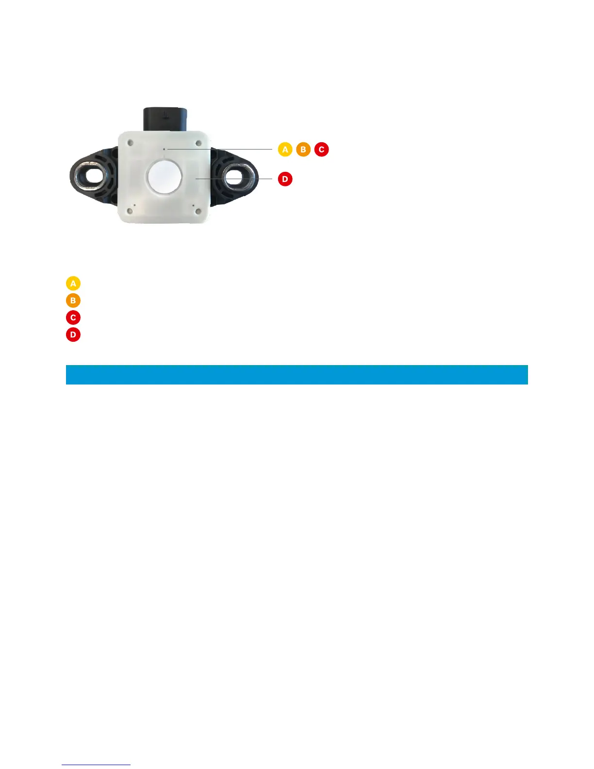
The CISS printed circuit board (PCB) includes LEDs, which indicate various states.
The LEDs on the back side of the CISS indicate the following:
Flashing LEDs
Yellow: The Bluetooth radio is advertising
Orange: The Bluetooth connection is established
Red: The CISS firmware is running
Red: This LED is used for Bosch-internal testing and can be ignored by the user
(only for CISS w/o battery with production date 2017).
INFO: The measurement of the illumination is not influenced by the flashing LEDs.
4.13 Memory
The CISS contains a 2 MB user data memory, which is accessible as a mass storage device over USB. It is used for local
logging of measurement data.
4.14 Communication interfaces
The CISS includes two communication interfaces - Bluetooth Low Energy (BLE) and Universal Serial Bus (USB) described
in the following.
The protocols and data formats are described in chapter 7.
BLE
Currently, Bluetooth Low Energy V4.0 is supported with the CISS always acting as a peripheral device, to which other BLE
devices like smartphones, tablets, etc. can establish a connection.
The Bluetooth communication interface is used, e.g. by a gateway or a mobile app, to:
Configure the CISS
Transfer data
USB
The USB communication is established via the USB cable (scope of delivery) and the connector at the CISS housing.
The cable is supplied with a standard USB A connector on one end and the CISS connector
(4way 1.2 SealStar FA Connector 805-122-541) at the other end.