12
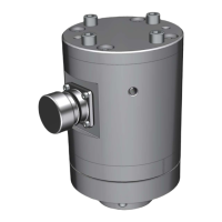
INFO: PIN configuration CISS connector (4way 1.2 SealStar FA Connector 805-122-541)
1 – USB_VBUS
2 – UBS_DP
3 – UBS_DM
4 – GND
The CISS microcontroller is a USB 2.0 full speed capable device.
The USB interface is used for:
Power supply (5V USB port)
Configuration of the CISS
Data transfer
INFO: Please find the communication protocols for BLE (CISS BLE Communication Protocol)
and USB (CISS USB Communication Protocol) as separate documents at:
www.bosch-connectivity.com/media-and-downloads/.
5 First steps
5.1 Mounting the CISS
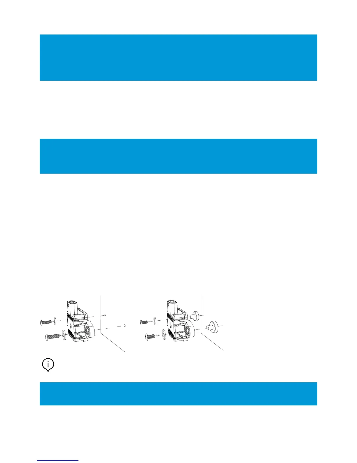
For mounting, the CISS housing has two side brackets. These can be used with screws (direct mounting) or with screws and
magnets (magnetic mounting). The scope of delivery contains:
Magnets
Washers
Screws
for mounting the CISS with the black side on top.
Direct mounting Magnetic mounting
Note: The use of the mounting magnets influences the measurements of magnetic fields.
The mounting magnets should not be used if the magnetometer is activated.
INFO: Please fix the provided screws (M4 x 8) hand-tightend via a 2.5 hexagon socket screwdriver. Depending
on the target mounting place, the provided screws might not fit - please use appropriate screws for target.