Installation
57
Climate 5000i – 6721824787 (2021/09)
3.5 Electrical connection
3.5.1 General notes
WARNING
Risk to life from electric shock!
Touching live electrical parts can cause an electric shock.
▶ Before working on electrical parts, disconnect all phases of the
power supply (fuse/circuit breaker) and lock the isolator switch to
prevent unintentional reconnection.
▶ Work on the electrical system must only be carried out by an
authorised electrician.
▶ Observe safety measures according to national and international
regulations.
▶ If you identify a safety risk in the mains voltage, or if a short circuit
occurs during installation, inform the operator in writing and do not
install the appliances until the problem has been resolved.
▶ All electrical connections must be made in accordance with the
electrical connection diagram.
▶ Only use a special tool to cut cable insulation.
▶ Do not connect any additional consumers to the mains power supply
of the device.
▶ Do not mix up live and null wires. This can lead to malfunctions.
▶ If the mains power supply is fixed, install an overvoltage protector
and isolator which is designed for 1.5 times the maximum power
input of the appliance.
▶ For devices with a fixed mains power supply in which the leakage
current is potentially higher than 10 mA, we recommend installing a
residual current device (RCD) with a maximum rated residual
operating current of 30 mA.
3.5.2 Connecting the indoor unit
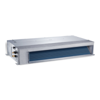
The indoor unit is connected to the outdoor unit using a 5-core
communication cable of the type H07RN-F. The conductor cross-section
of the communication cable should be at least 1.5 mm
2
.
NOTICE
Material damage due to incorrectly connected indoor unit
Voltage is supplied to the indoor unit via the outdoor unit.
▶ Only connect the indoor unit to the outdoor unit.
To connect the communication cable:
▶Fold up the top cover ( Fig. 19).
▶ Undo screw and remove cover of the interface panel.
▶ Remove screw and cover [1] of the terminal ( Fig. 20).
▶ Knock out an opening for the cable feed [3] on the rear of the indoor
unit and feed the cable through.
▶ Secure cable to the strain relief [2] and connect to the terminals W,
1(L), 2(N), S and .
▶ Note assignment of wires to the terminals.
▶ Reattach the covers.
▶ Route the cable to the outdoor unit.
3.5.3 Connecting the outdoor unit
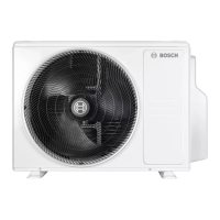
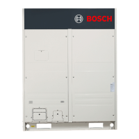
A power cable (3-core) is connected to the outdoor unit and the
communication cable is connected to the indoor unit (5-core). Use
cables of the type H07RN-F with sufficient conductor cross-section and
protect the mains power supply with a fuse ( Table 8).
Table 8
▶ Undo the screw and remove the cover of the electrical connection
( Fig. 21).
▶ Secure the communication cable to the strain relief and connect to
the terminals W, 1(L), 2(N), S and (assignment of wires to
terminals same as indoor unit) ( Fig. 22).
▶ Secure power cable to the strain relief and connect to the terminals
L, N and .
▶ Reattach cover.
Outdoor unit Mains fuse
protection
Conductor cross-section
Power cable Communication
cable
CL5000i 26 E 13 A ≥ 1.5 mm
2
≥1.5mm
2
CL5000i 35 E 13 A ≥ 1.5 mm
2
≥1.5mm
2
 Loading...
