10 en | Introduction and overview DCN-D Conference Delegate Units
F.01U.265.631 | V1.0 | 2012.03 Installation and Operation manual Bosch Security Systems B.V.
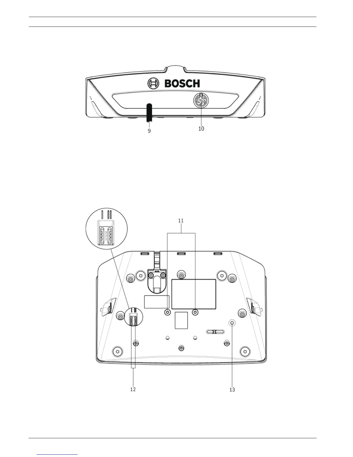
The rear side of the delegate unit contains:
9. DCN cable - Connects the delegate unit to the DCN system.
10. DCN socket - Makes a loop-through in the DCN system with the delegate unit.
Figure 3.4 Delegate unit rear view
The bottom side of the delegate unit contains:
11. Screw holes - Attach the delegate unit to a flat surface.
12. Configuration switches - Configuration of the delegate unit and sets the mode of the
delegate unit.
13. De-init switch - Erases the address of the delegate unit.
– All LEDs on the delegate unit are on when the delegate unit does not have an
address.
Figure 3.5 Delegate unit bottom view