Do you have a question about the Bosch Digital Congress Network and is the answer not in the manual?
Units participants use to contribute to a conference, offering various facilities like speaking and voting.
The heart of the DCN system, the CCU controls up to 240 contribution units; slave CCUs extend capacity.
Facilities for simultaneous interpretation and language distribution via wired or wireless systems.
DCN system distributes information to participants via LCD personal screens or video equipment.
Software packages run under Windows for conference management and control, offering various functions.
Fast cost-saving installation using thin twin-coaxial cable, eliminating costly multi-core cables.
Overview of DCN functions for stand-alone and PC-controlled systems, including microphone management.
Lists various software packages available for DCN systems, covering functions like voting, interpretation, and database management.
DCN contribution equipment categorized into table-top, table-top + flush mounted, and flush mounted.
Table-top units include delegate, chairman, and interpreter units designed for uncluttered placement.
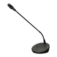
Delegate units allow participation in proceedings, enabling speech, listening, and voting.
Chairman units have priority buttons to control discussions and mute other microphones.
Function for podium/floor speakers or installations without delegate units, connecting mics to audio interface units.
Interpreter desks handle multiple language channels for bi/multi-lingual conferences efficiently.
Delegate units for speaking, request-to-speak, and listening, with LBB 3531/xx including a channel selector.
Chairman units include a priority button for discussion control, overriding and muting other microphones.
Delegate and chairman units' functionality can be set via solder spot J1 for features like flashing LED rings.
Discussion units use connectors for loop-through connection, allowing daisy-chaining.
Units can be free-standing or nut/bolt mounted in permanent installations using threaded holes.
Table-top/flush-mounting delegate units for discussion, with LBB 3545/00 and 3546/00 including language channel selectors.
Chairman units provide microphone control, voting, and language selection, with a priority key for meeting control.
Concentus units' functionality can be set via solder spots 1070, 1170, 1171, and 1172 on the PCB.
Unidirectional microphones for delegate/chairman units and flush-mounted control panels, featuring an illuminated indicator ring.
Handset enables private two-way vocal communication between conference participants and interpreters.
Flush-mounted units for fixed installations, offering functions similar to table-top units and available in standard sizes.
Unit connects various microphones and line sources to the DCN system, supporting two delegate/chairman positions.
Describes flush mounting solutions for delegate and chairman positions using various DCN units.
Unidirectional microphones with built-in pop and windshield, connecting to audio interface or multi-purpose units.
Versatile unit for flush-mounted solutions, adding functions like voting control and ID card reader.
Illustrates flush-mounted solutions (No.5 and No.6) for delegate positions using LBB 3540/15.
Illustrates flush-mounted solutions (No.7 and No.8) for delegate and chairman positions using LBB 3540/15.
Delegate microphones mounted on flush panels, connecting to multi-purpose or audio interface units.
Chairman microphone control panel with priority button, used with pluggable microphones for chairman positions.
Microphone control panel for pluggable microphones, connecting to multi-purpose or audio interface units.
Loudspeaker panel used with flush-mounted units for distributing floor signals.
Voting control panel enabling delegates to participate in set voting sessions, connecting to multi-purpose units.
Voting and message display panel with LC-display, usable for both delegate and chairman positions.
Chip-card reader for electronic delegate identification and access control in DCN systems.
Set of 100 chip cards for delegate identification, access control, and other utility functions.
Chip card encoder for encoding cards compliant with ISO standards, integrated into DCN systems.
Channel selector panels with numeric display and up/down keys for language selection via headphones.
Enables or disables the unit's 'Auto Switch-Off' function, which switches off the unit when headphones are removed.
Housing for portable/table-top systems, neatly accommodating electronic channel selector or voting control panels.
Blank panels used to cover redundant flush-mounted table-top slots for future system expansion.
Table-top housing accommodating flush-mounted units and loudspeaker panels, designed for easy installation.
Interpreter desk with facilities for up to 15 language channels, including manual and PC-programmed settings.
Details the listening, incoming channel, speaking, viewing functions, and interconnections of the interpreter desk.
Procedure for removing the cable guide from the interpreter desk to access the cable guide groove.
Instructions for mounting the intercom handset to the interpreter desk using a metal mounting plate and screws.
Module for connecting external analog audio equipment to DCN for distribution and monitoring.
The Central Control Unit (CCU) is central to the DCN system, controlling up to 240 units, usable stand-alone or PC-controlled.
Basic CCU for stand-alone discussion systems, handling up to 240 units and 90 PCF points, with basic operational modes.
CCU for stand-alone and PC-controlled systems, supporting up to 180 PCF points and offering extended facilities via PC software.
Multi-CCU extends system capacity up to 3840 units, controlled by a master PC with specific software and hardware.
Details front and rear panel controls and indicators for the LBB 3500/35 Multi Central Control Unit.
Instructions for setting CCU mains voltage and ensuring proper earthing and connection.
Information on the supplied 3-core mains cable and its connection to the CCU and mains outlet.
Details the location of the CCU mains fuse and replacement fuse ratings, emphasizing the need for an earthed mains outlet.
Describes the TCB4 board, its RS232 ports for PC and camera control, and its installation.
Explains the functionality of DIP-switch S9 on the TCB4 for various operational modes like chairman priority and audio modes.
Details the function of jumpers X13 and X14 on the TCB4 for SRAM battery backup and watchdog activation.
Configuration of protocol and serial port settings (S14 DIP-switches) for CCU ports, including default settings.
Card installed in CCUs to connect other Multi-CCU units, extending system capacity, with details on address setting and installation.
Defines the cards 'Slave Address' using DIP-switches 4-8, with fixed settings for switches 1-3.
Defines the cards I/O settings (04E0 HEX) using DIP-switch S13, with default settings and available addresses.
Details how to connect external equipment like recording devices, PA systems, and mixing desks to the CCU.
Introduces new audio routing modes 'MIX-MINUS' and 'INSERTION', selectable via DIP-switches S9.
INSERTION mode interrupts normal audio path for external device connection, like an audio mixer.
Remotely controlled unit extending system power for up to 180 PCF points, connecting to trunk-line cabling.
Unit connects external analog equipment to DCN, enabling connection of up to 90 PCF points and using loop-through cabling.
Central Control Units can be rack-mounted into a 19” rack or placed on a table-top, ensuring adequate ventilation.
Specifies PC requirements for Windows 95/98 and NT/2000/XP, including processor, memory, and storage.
Network card for ISA-bus expansion slots, providing PC interface to DCN system with headphone and intercom sockets.
Steps for installing the PC-Network card, ensuring mains supply is OFF and correct voltage selection.
Details PC to DCN cabling via Network card or 'DIRECT' serial link, including intercom handset and headphone connections.
Interface card for master PC to CCU connection, installed in secondary PC running OS/2 for Multi-CCU network.
Configuration of DIP-switches S12 and S13 on the PC card for assigning digital input and I/O addresses.
Describes two methods for connecting DCN Control PC to CCU: 'DIRECT' serial link or PC-Network card.
Illustrates a single CCU system connection with control PC and camera control, detailing RS232 connections.
Shows a Multi-CCU system connection with control PC and camera control, involving master CCU PC and multiple CCUs.
Explains PC network installation for multiple operator control positions using Ethernet cards and peer-to-peer networking.
Details CCU_CFG file settings for serial COM-ports on the Master CCU PC, including port number, speed, and protocol.
Provides example CCU_CFG file settings for direct PC and camera control configurations.
Shows single COM-port settings for remote control, camera control, and DCN PC control.
Details COM-port configurations for remote control, camera control, and DCN PC control using two COM ports.
Maps DCN software packages to printer and COM-port assignments for PC-controlled systems.
Maps DCN software packages to printer and COM-port assignments for systems using 'DIRECT' PC control.
Details connections for Matrix printers, Chip-card encoders, and Laser printers via serial and parallel ports.
Allegiant Video Switchers and associated equipment used for DCN Automatic Camera Control (DACC) for switching cameras towards speakers.
Keyboard required for manual control and programming of Allegiant switchers, enabling preset definition and picture selection.
Details available fixed and orientable cameras, preferred color cameras, and video displays for operator and audience viewing.
Requirements for installing Allegiant Video Switcher panels, cameras, and monitors, and connecting them to the DCN system.
Configuring and setting up camera positions based on delegate/chairman microphone activity using DACC software.
Procedure for camera installation with stand-alone Camera Control software requiring temporary PC connection.
Steps for connecting a temporary PC to the CCU and Allegiant Video switcher for single CCU configurations.
Steps for connecting a temporary PC to the CCU and Allegiant Video switcher for Multi-CCU configurations.
Default COM port settings for PC communication with CCU and video switcher, and how to specify custom settings.
DCC allows connecting one AutoDome camera directly to a CCU for directing towards speakers, with specific system requirements.
Virtual keyboard software used to set AutoDome camera pre-positions, requiring installation on a temporary or control PC.
Connecting a BOSCH AutoDome camera with RS232 control to the CCU and video displays accepting PAL-B or NTSC signals.
Shows required cables for connecting single CCU to camera, PC to CCU/camera, and PC to CCU and camera.
Using PC COM-port 2 and video control matrix to switch and direct video cameras based on delegate microphone activity.
Installation accessories simplify DCN system setup using ready-made cables, connectors, and trunk-cable splitters.
Splitter divides trunk-line cabling into diverse directions for neat layout and equipment connection.
Unit creates short-circuit proof tap-off points on trunk-line cabling, allowing connection of channel selector panels or contribution units.
Details available cable assemblies and connectors, including trunk-cable splitters and tap-off units, for extending DCN system cabling.
Describes 6-pole moulded circular connectors and recommends insulated metal shield connectors for extension cables.
Clamps for male/female cable connectors, used with extension cables LBB 4116 for secure connection.
Termination plug for open-ended DCN cabling, connected to the last channel selector panel in a daisy-chain.
Board provides communication interface for hall displays, remote switching panels, and tailored conference solutions via RS232.
Details connectors, controls, and indicators on the Data Distribution Board LBB 3512/00, including DIP-switch settings.
Interface facility for controlling external equipment like loudspeaker group switching using the Data Distribution Board.
Procedure for mounting and connecting the data distribution board inside hall displays and to the DCN system trunk-line.
Example layout for connecting hall displays to the DCN system using trunk-splitters and extension cables.
Connecting client PCs with video display software to the main DCN PC (server) via Ethernet for displaying information.
DCN system can connect to external devices like telephone couplers for enhanced functionality.
Interface connects DCN system to public telephone network, enabling remote participation and interpretation.
Focuses on system installation techniques, examples, and limitations for stand-alone and PC-controlled systems.
Introduces power handling requirements and control limitations of DCN systems, emphasizing PCF values and calculation.
Explains Power Consumption Factor (PCF) and its bearing on the total number of units connectable to a system, including calculation graphs.
Describes Trunk outlets and Tap-offs on units like Extension Power Supply, Audio Media Interface, and Trunk-cable splitter.
Specifies limitations on serial tap-off connections from CCU to the last tap-off in a chain.
Details the Tap-off unit's short-circuit protection and capacity for connecting various units.
Outlines maximum cable lengths for DCN system units, affecting PCF value and system limits.
Guide on calculating PCF values considering cable length using PCF tables and graphs.
Step-by-step guide to calculate PCF values by considering unit PCF, cable length, and cable correction graphs.
Explains how to interpret the graph for calculating PCF values based on trunk-outlet and extension cable length.
Provides examples of PCF calculation for a single trunk-outlet using PCF graph and block diagrams.
Details the control capacity of CCUs (active and passive units) and how to extend it with Multi-CCU systems.
Explains stand-alone systems using extension cables, trunk-splitters, and tap-off units for cabling and layout.
Illustrates a basic trunk-line interconnection without using extension units.
Shows unit layout possibilities using trunk-splitters and extension cables for lengthening cable runs.
Illustrates typical system interconnections, both centralized and de-centralized, with extension units.
Describes two methods for connecting a central control PC: DIRECT and IN-DIRECT connections.
Configuration for PC network systems with multiple operator control positions using Ethernet cards and peer-to-peer networking.
Multi-CCU systems cater for over 240 units, controlled by a dedicated PC with Multi-CCU software.
Details PC setup and interconnection for Multi-CCU systems using BNC cables and recommended software.
Facility for connecting a remote controller for microphone management, voting, and attendance registration.
Instructions for installing remote control software on a remote PC and connecting it to the CCU via RS232.
Examples of assigning microphones to push-buttons and managing microphone modes using the remote controller.
Details on interconnecting interpreter desks using loop-through cabling or tap-off units.
Interpreter desks use similar interconnection facilities as delegate/chairman units, connecting in series or via tap-off units.
System layout using trunk-splitters and tap-off units for arranging interpreter desks in booths.
Methods for distributing interpreted languages to delegates via wired or wireless systems.
Distribution of interpreted languages via wired (channel selectors) or wireless (infra-red) systems.
Installation of wired language distribution systems using table-top units or flush-mounted electronic channel selector panels.
System initialization required to recognize DCN units and allocate addresses via the CCU.
Procedure for initializing a stand-alone system by de-initializing and then initializing each unit.
Initialization for PC-based systems is similar to stand-alone, but allows linking seat numbers via System Installation Software.
Stand-alone systems enable microphone management, voting, interpretation, and intercom operations.
Selecting between Single or Multi-CCU mode for LBB 3500/35 using the 'System' push-button.
CCU offers three microphone modes: 'Open', 'Override', and 'Voice Activation', with selectable active microphone limits.
Steps for setting up Multi-CCU systems, including PC-card installation, unit connection, address setting, and software installation.
Procedure to download software from DCN control PC to CCUs and configure system settings via 'System Config'.
Maintenance menu for stand-alone systems allows setting default language and intercom operator position.
Procedure to set the display language for all units with LC-displays via the Maintenance Menu.
Procedure to assign a unit as the 'Intercom Operator' position via the Maintenance Menu.
Includes equalizer function for optimizing speech intelligibility and controls for setting system volume/gain levels.
Built-in audio equalization facility in CCU to optimize audio characteristics of DCN unit loudspeakers.
Rotary controls for setting overall system gain/volume for DCN contribution unit loudspeakers.
Stand-alone operations include electronic voting and intercom facilities for delegate/chairman units and interpreter desks.
Electronic voting procedure for meeting requirements, initiated by chairman unit, supporting Parliamentary voting.
Intercom handset allows two-way conversation with an assigned central Intercom Operator.
Explains microphone management and unit descriptions for delegate and chairman units.
Microphone management techniques for delegates to use their microphone units, controlled by central operator via DCN software.
Details operation of Delegate units, including microphone status indicators, controls, and connections.
How to switch microphone ON/OFF, indicators for status, and handling of external microphones.
Selecting desired simultaneous interpretation language channels using the units LC display and keys.
Ensures authorized users access unit functions by inserting an ID-card in PC-operated systems.
Navigating menus (MICRO, VOTING, MESSAGE) via graphic LC-display and soft-keys for status, voting, and messages.
Initiating and participating in voting sessions using softkeys for Parliamentary voting or other options.
Details operation of Chairman unit, including microphone functions, priority key, language selection, and ID-card reader.
How to switch microphone ON/OFF, indicators, and priority key functions for chairman units.
Selecting interpretation language channels via LC display and controls.
Chairman unit access function using ID-card reader for authorized use.
Navigating menus (MICRO, VOTING, MESSAGE) on the chairman unit's LC display.
Initiating and participating in voting sessions using softkeys.
Displaying incoming messages sent by PC operator via message application software.
Details operation of delegate and chairman units in discussion systems, covering microphone functions and priority.
Switching microphone ON/OFF, LED indicators for status, and using headphones for listening.
Priority button allows chairman to override/mute other active microphones, with optional chime tone.
Selecting interpretation language channels using LC display and select keys, and adjusting headphone volume.
Interpreter desk functions including operational and programming modes, listening and speech sections.
Selecting incoming language via rotary switch and pre-select keys, with quality indication on LC-display.
Distributing translations via outputs A and B, with options for auto-relay and relay interpretation.
Microphone on/off switch, mute button, and indicators for microphone status.
Programming 'Override' or 'Interlock' functions for microphones between booths or within booths.
Function allowing interpreters on the same output channel to override each other on a First-In-First-Out basis.
Function permitting only one microphone per channel at a time, preventing other interpreters from using the same channel.
Allows simultaneous microphone activation on the same channel without override or interlock facilities.
Procedures for interpretation when floor language is unfamiliar, using auto-relay facility for translation.
Details incoming channel selection, pre-select key assignment, floor switch, and language quality indication.
Using pre-select keys (a, b, c) to quickly select familiar incoming languages for translation.
Procedure for assigning incoming languages to pre-select keys (a, b, c) using the relay select knob.
Switching between floor or auto-relay channels using the incoming floor key.
Indication of incoming language quality (direct, indirect translation) displayed on the LC-display.
Using tone controls and volume control for headphones/headsets, and built-in loudspeaker for floor language monitoring.
Selecting outgoing language channels via A-output, A+B-output, and A+B-output with Auto-relay facility.
Displays showing incoming and outgoing language channels, engaged LEDs, and microphone operation.
Entering programming mode to manually set interpreter desk parameters prior to a conference.
Using LC-display and menu system to program user language, booth number, desk number, and channels.
Procedure to enter the interpreter desk's programming mode by pressing specific keys.
Step-by-step guide for navigating menus, selecting options, and confirming entries during programming.
Setting the required language for display during desk programming.
Assigning the interpreter desk to a specific booth, programmed individually.
Assigning a specific number to the interpreter desk within a booth.
Setting the number of language channels available, dependent on system type (stand-alone or PC-based).
Selecting a list of languages and their abbreviations for display.
Assigning languages to channels for interpreter selection, dependent on channels set in menu d.
Setting the desk's A-output channel number for language distribution.
Setting the interpreter's B-output to NONE or ALL channels for language distribution.
Assigning the number of booths that supply an auto-relay function for interpretation systems.
Selecting the auto-relay booth number for interpreter desks.
Enabling 'Override' or 'Interlock' facility for microphone control between booths.
Guidelines for using cable ducts, identifying cables, and positioning units for proper installation and protection.
Recommendations for public areas, including lighting, display placement, walkways, and headphone usage.
Recommended conditions for technical rooms housing DCN equipment, focusing on ventilation, dust-free environment, and temperature control.
Specifications for interpreter booths, including construction, dimensions, glass requirements, and environmental controls.
Maintaining good ventilation for central control units by positioning them on level surfaces away from walls.
Instructions for cleaning equipment using mild soap and water, avoiding abrasive cleaners or solvents.
Guidelines for storing mains-supplied units when not in use, emphasizing dust-free, dry areas with adequate ventilation.
Provides metric/imperial conversion and mechanical specifications for Central Control Units, including dimensions and weight.
Mechanical data for LBB 3500 series CCUs, covering mounting, dimensions, and weight.
Details mounting brackets used for central control equipment and extension units, noting two brackets are supplied per unit.
Mechanical data for extension power supply units, including mounting, dimensions, and weight.
Mechanical data for audio media interface units, including mounting, dimensions, and weight.
Technical data for table-top units, including conference units, delegate units, pluggable microphones, and interpreter desks.
Mechanical data for delegate/chairman and delegate units (Concentus), including dimensions and weight.
Mechanical data for delegate and chairman discussion units, including dimensions and weight.
Mechanical data for the Dual Audio Interface Unit, including mounting, dimensions, and weight.
Mechanical data for hand microphones, including dimensions and weight.
Mechanical data for intercom handsets, including dimensions and weight.
Mechanical data for channel selector housing, including mounting, cable out, dimensions, and weight.
Mechanical data for table-top housing for FM loudspeaker panels, including mounting and dimensions.
Technical data for flush-mounted equipment, including channel selector panels and microphone control panels.
Mechanical data for FM Electronic Channel Selector Panels, including mounting, dimensions, and weight.
Mechanical data for FM Electronic Channel Selector Panels, including mounting, dimensions, and weight.
Mechanical data for microphone control panels, including mounting, dimensions, weight, and microphone height.
Mechanical data for chairman priority control panels, including mounting, dimensions, weight, and microphone height.
Mechanical data for blank panels, including mounting and dimensions.
Mechanical data for FM microphone control panels, including mounting, dimensions, weight, and microphone height.
Mechanical data for FM loudspeaker panels, including mounting, dimensions, and weight.
Mechanical data for multi-purpose connection units, including mounting, dimensions, and weight.
Mechanical data for delegate voting control panels, including mounting, dimensions, and weight.
Mechanical data for delegate/chairman voting control panels with LC-display, including mounting, dimensions, and weight.
Mechanical data for chip card readers, including mounting, dimensions, and weight.
Technical data for installation accessories like trunk cable splitters and tap-off units.
Mechanical data for trunk cable splitter and tap-off units, including mounting, dimensions, weight, and cable bending angle.
Electrical specifications for microphones, headphones, transmission links, and combined units.
General electrical specifications for microphones, including frequency response, transducer type, and sensitivity.
Electrical data for various headphone types (stereo, under-chin, interpreter, single-earphone, dynamic).
Electrical data for transmission links, covering frequency response, harmonic distortion, crosstalk, and dynamic range.
Electrical data for combined units like delegate microphone with transmission links to various outputs.
System electrical characteristics including nominal input level, overload level, and gain controls.
Environmental conditions for system operation, including temperature range, humidity, safety standards, and EMC.
Interface data for LBB 3500/.. CCU and LBB 3508/00 Audio Media Interface Unit.
Mains supply voltage details for CCUs and related units, including upon delivery voltage.
Nominal power consumption for various CCU and related units.
System limitations regarding maximum cable lengths, tap-off connections, and unit series connections based on PCF.
Details on mains cable wiring, DCN circular connectors, and cable connections for pluggable microphones.
Connection details for CONCENTUS units using 5-pole XLR female connectors.
External microphone connection for CONCENTUS units using 3.5 mm jack plugs.
Cable connection details for CINCH connectors.
Details for jack-plug connections (Tip, Ring, Sleeve).
Headset connector details for interpreter desks according to IEC 268-11.
Pin configuration for the 15-pole D-type connector PC interface.
| Frequency range | 20 Hz - 20 kHz |
|---|---|
| Total harmonic distortion | < 0.1 % |
| Operating voltage | 100-240 VAC, 50/60 Hz |
| Audio Channels | Multiple (configurable) |
| Connectivity | Ethernet |
| Microphone Control | Yes |
| Simultaneous Interpretation | Yes |
| Recording | Yes |
| Central Control Unit | Included |
| Power consumption | Depends on configuration |
| Dimensions (H x W x D) | Varies depending on specific unit |
| Weight | Varies depending on specific unit |
| Storage temperature | -20°C to +70°C (-4°F to +158°F) |