579604 | REV. C | June 2020
Bosch Automotive Service Solutions Inc.
en
| 6 |
EV2000 Series Wallbox Charger Installation and Operation Manual
Installation and Operation Manual
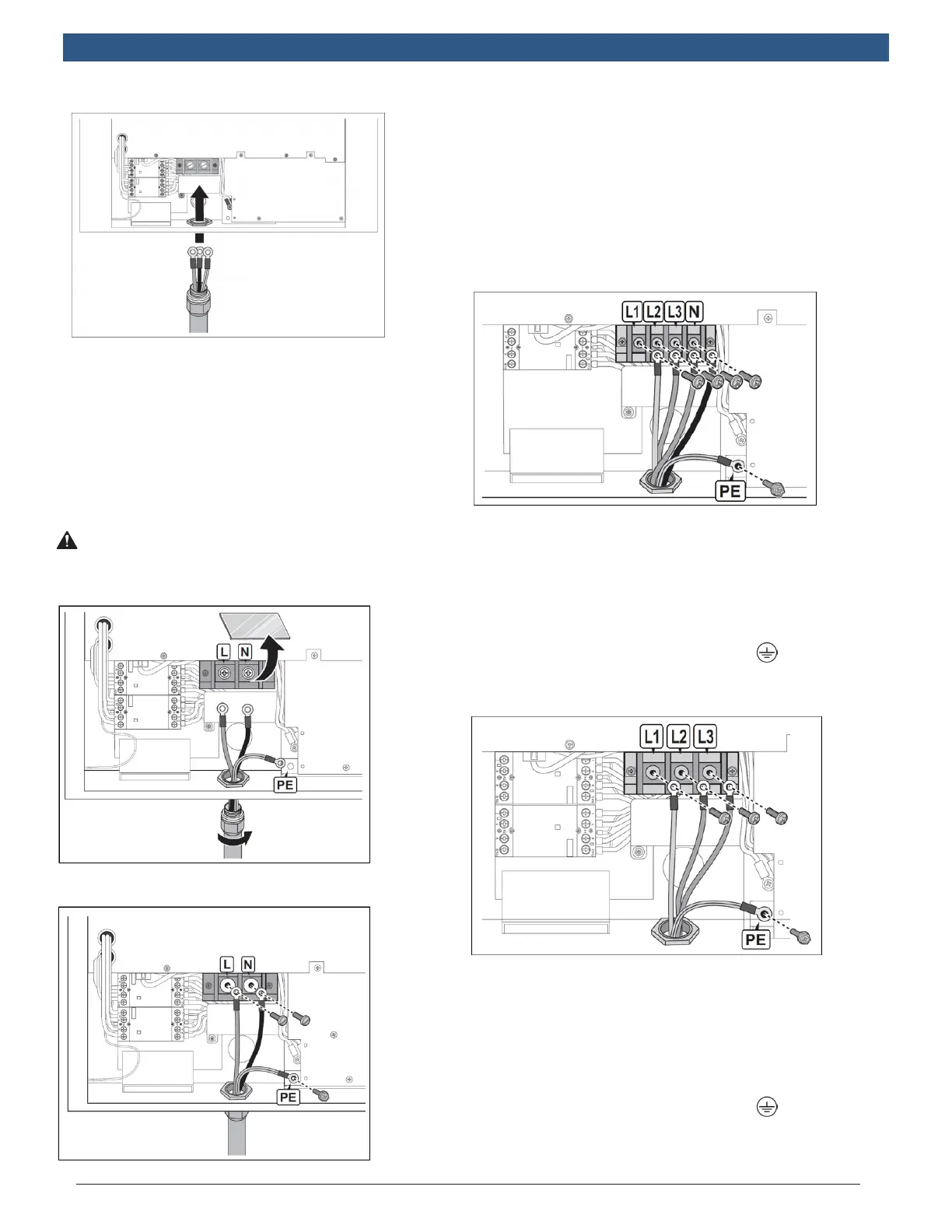
3. Fasten cable gland to secure wires.
NOTE: To ensure protection from the elements, make
sure to use certied IP55 (or above) cable
glands.
4. Remove lid of terminal block and connect the wiring
to the correct terminals. See the following informa-
tion for specic model connections.
Wiring requirements are dependent on the model
type and between single and three-phase models.
WARNING! Cable color coding may be
dened differently depending on the
region.
Single-Phase: Wiring the 240 / 277V Models
` Conduit hub and conduit size M50 according to EN
61386-24.
` Connect the power wires of 2 x RNB70-10 ring terminal
with cable lugs to the input terminal marked with “L”
and “N” using 2 x M10.0 screws with torque of 88.4
lb-in.
` Connect the ground wire of RNBS14-6 into the earth
terminal marked with ground symbol using 1 x M6 screw
with torque of 17.7 lb-in.
Three-Phase: Wiring the 480V Model
` Conduit hub and conduit size M50 according to EN
61386-24.
` Connect the power wires of 4 x RNB14-6 ring terminal
with cable lugs to the input terminal marked with “L1”,
“L2”, “L3” and “N” using 4 x M6.0 screws with torque of
28.7 lb-in.
` Connect the ground wire of RNBS14-6 into the earth
terminal marked with ground symbol ( ) using 1 x M6
screw with torque of 17.7 lb-in.
Three-Phase: Wiring the 208V Model
` Conduit hub and conduit size M50 according to EN
61386-24.
` Connect the power wires of 3 x RNB38-6 ring terminal
with cable lugs to the input terminal marked with “L1”,
“L2” and “L3” using 3 x M6.0 screws with torque of 28.7
lb-in.
` Connect the ground wire of RNBS14-6 into the earth
terminal marked with ground symbol ( ) using 1 x M6
screw with torque of 17.7 lb-in.
` Neutral wire is not required.