English | 13
Once the measurement is complete, the result
for the required distance "X" is displayed in
the result line (c). The measured values for dis-
tance "1" and angle "α" can be found in the
measured value lines (a).
b) Double indirect height measurement (see figureD)
Repeatedly press the button for changing function (4) until
the indicator for double indirect height measurement
ap-
pears on the display.
Measure distances 1 and 2 in succession as for a length
measurement.
Once the measurement is complete, the result
for the required distance X is displayed in the
result row (c). The measured values for dis-
tances 1 and 2 and angle α can be found in the
measured value rows (a).
Ensure that the reference level for the measurement (e.g.
the rear edge of the measuring tool) remains in exactly the
same place for all the individual measurements in a single
measuring process.
c) Indirect length measurement (see figureE)
Repeatedly press the button for changing function (4) until
the indicator for indirect length measurement
appears on
the display.
Ensure that the measuring tool is at the same height as the
required measuring point. Then tilt the measuring tool
around the reference level and measure distance "1" as for a
length measurement.
Once the measurement is complete, the result
for the required distance "X" is displayed in
the result line (c). The measured values for dis-
tance "1" and angle "α" can be found in the
measured value lines (a).
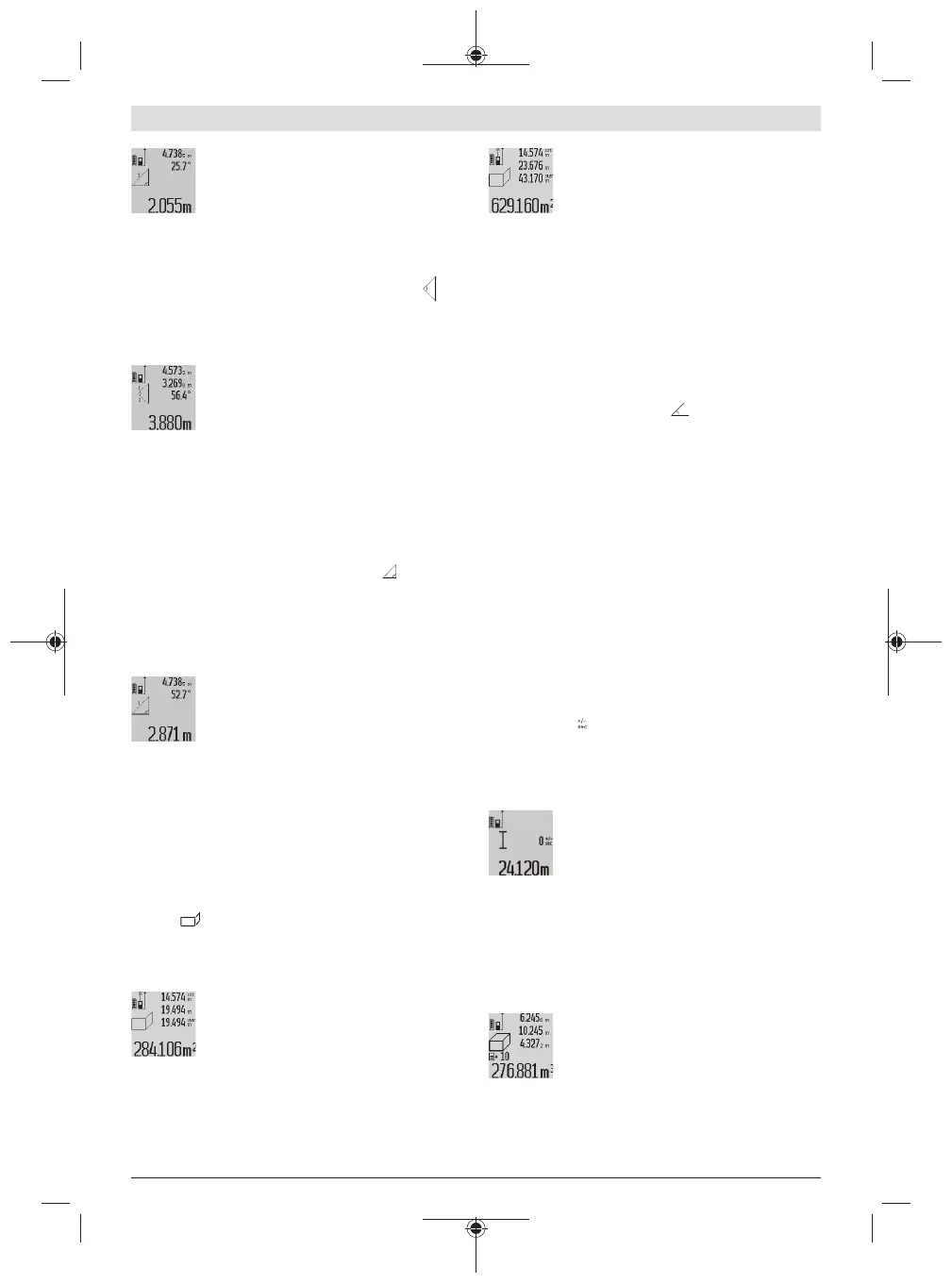
Wall area measurement (see figureF)
The wall area measurement is used to determine the sum of
multiple individual areas with a common height.
In the illustrated example, the total area of several walls that
have the same ceiling height A but different lengths B is to
be determined.
For wall area measurements, repeatedly press the button for
changing function (4) until the indicator for wall area meas-
urement appears on the display.
Measure the ceiling height A as with a length measurement.
The measured value ("cst") is displayed in the top measured
value line (a). The laser remains switched on.
Then measure the length B
1
of the first wall.
The area is automatically calculated and dis-
played in the result line (c). The last measured
value for length can be found in the middle
measured value line.(a). The laser remains
switched on.
Now measure the length B
2
of the second wall.
The individual measured value displayed in the
middle measured value line (a) is added to the
length B
1
. The sum of the two lengths ("sum",
displayed in the bottom measured value line
(a)) is multiplied by the saved height A. The total area value
is displayed in the result line (c).
You can measure any number of lengths B
x
, which will be
automatically added and multiplied by the height A.
The requirement for a correct area calculation is that the first
measured length (for example the ceiling height A) is
identical for all sub-areas.
Grade measurement (see figureG)
Press the button for grade measurement (3) to bring up the
indicator for grade measurement on the display. The rear
of the measuring tool serves as the reference level. Press the
button for grade measurement (3) again to use the sides of
the measuring tool as a reference level and rotate the display
view by 90°.
Press the measuring button (2) to fix the measured value
and transfer it to the measured value memory. Press the
measuring button (2) again to continue the measurement.
If the display flashes during measurement, the measuring
tool has been tipped too heavily to the side.
If the "digital spirit level" function is activated in the basic
settings, the grade value is also displayed in the other meas-
uring functions in line (d) of the display (1).
Timer function
The timer function is useful when the measuring tool should
be kept stationary during measurement, for example.
Press and hold the button for the timer function (6) to bring
up the indicator on the display.
The time period between triggering the timer and starting
measurement is displayed in the measured value line (a).
The time period can be set between 1–60 seconds by press-
ing the plus button (11) or minus button (5).
The measurement is made automatically after
the set time period has expired.
The timer function can also be used for dis-
tance measurements within other measuring
functions (e.g. area measurement). It is not possible to add
or subtract measuring results or carry out continuous meas-
urement.
List of the last measured values
The measuring tool stores the last 20 measured values and
their calculations and displays them in reverse order (with
the most recent measured value displayed first).
To retrieve the saved measurements, press the
button (7). The result of the last measurement
appears on the display, along with the indic-
ator for the measured values list (e) and with
storage space for the numbering of the dis-
played measurements.
If no further measurements are saved upon pressing the but-
ton (7) again, the measuring tool switches back to the last
Bosch Power Tools 1 609 92A 544 | (27.05.2019)
 Loading...