VG4 Modular Camera Series Installing the Pendant Arm Wall, Corner, and Mast (Pole) Mounts | en 27
Bosch Security Systems, Inc. Installation Manual F.01U.216.010 | 8.0 | 2011.02
5. Connect the incoming video coax cable to the BNC connector from the Pendant
Connector Harness and slide its plastic cover over the connector.
6. To connect alarm inputs and relay outputs, connect the 4-pin Alarms Out, the 6-pin
Alarms In and the 7-pin Relay connectors from the Pendant Connector Harness to their
mating connectors, installed previously, to the incoming alarm wires.
7. Connect the 3-pin Power In Plug, installed previously, to its matting connector P101 on
the left side of the box.
8. If installing a Fiber Optic model attach the incoming ST fiber plug, installed previously, to
its mating connector on the Fiber Optic Module in the power supply box. Then attach the
video BNC plug to its mating connector from the Pendant Connector Harness. See
Section 5 Cable and Wire Standards, page 88 for fiber optic specifications.
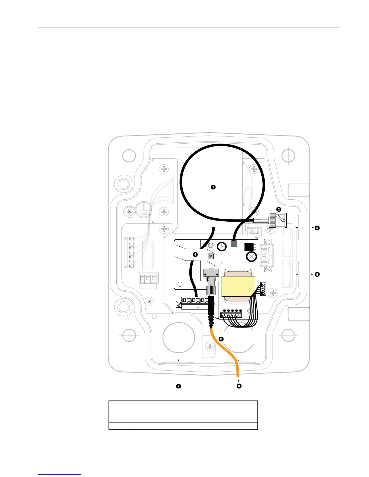
Figure 2.11 Optional Fiber Optic Module
1 Transformer 5 In/Out
2 BNC to Dome 6 ST Connector (Fiber)
3In/Out 7Power In
4 From Arm Harness 8 Data In/Out
(GND)
FUSE)
FUSE)
FUSE
24V N
24
 Loading...