80 en | Installing the In-Ceiling Mount VG4 Modular Camera Series
F.01U.216.010 | 8.0 | 2011.02 Installation Manual Bosch Security Systems, Inc.
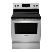
5. Tighten the four (4) securing screws to the Bracket Assembly.
Figure 4.4 Tighten Bracket Securing Screw
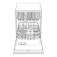
6. Secure the Bracket Assembly to an overhead securing point with a safety wire.
Figure 4.5 Secure Bracket Assembly
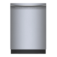
4.6 Wire the Interface Box
The Interface Box can be wired through the top or side. Use the supplied rubber plug to seal
the hole which will not be used to route wires.
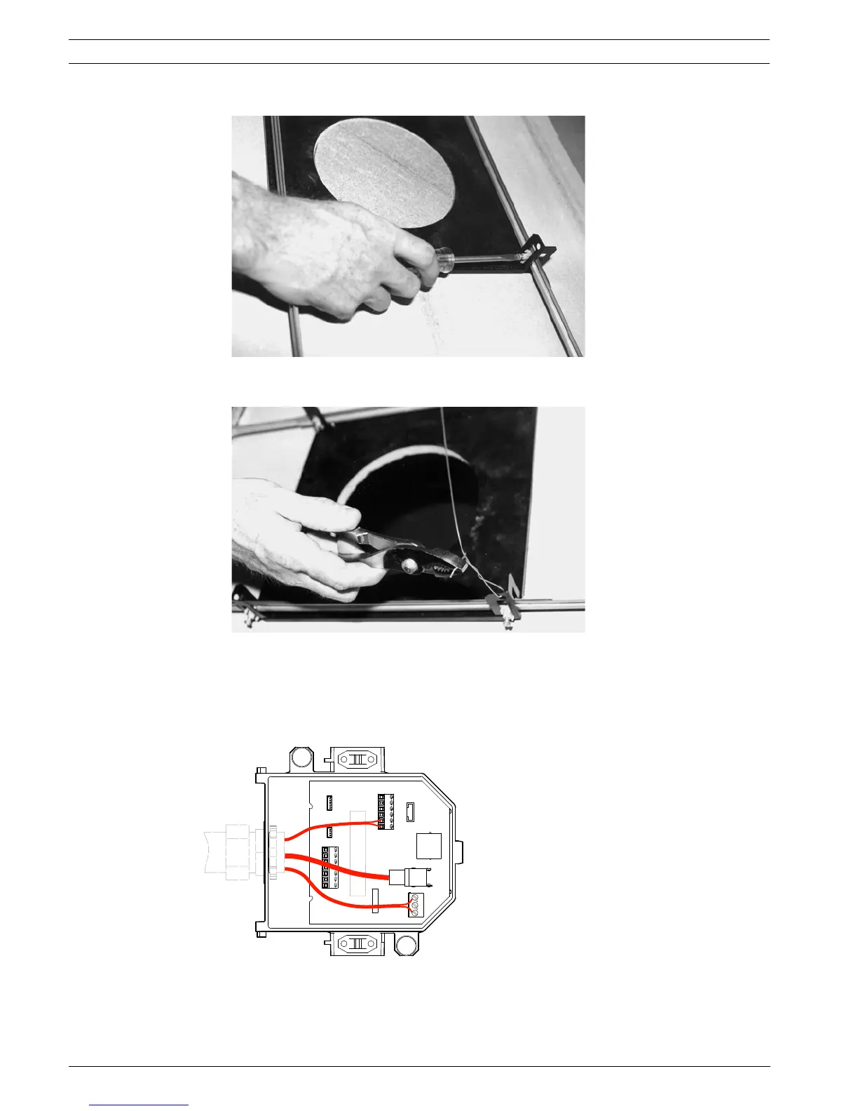
Figure 4.6 Interface Box Connections
DATA IN/OUT
ALARM IN
P105
P104
P102
P103
ANALOG IN RELAY
ALARMS
OUT
J101
J102
24VAC
24VAC
P101
SIG GND
TXD (-)
RXD (+)
+ C
- C
NC
NO
COM
AGND
A2
A1
FIBER OPTICS
J103
ETHERNET
OR UTP
VIDEO
DOME
POWER
COAX
VIDEO
A3
A4
A5
A6
A7
AGND
AGND
OUT3
OUT2
OUT1
 Loading...