VG4 Modular Camera Series Installing the In-Ceiling Mount | en 83
Bosch Security Systems, Inc. Installation Manual F.01U.216.010 | 8.0 | 2011.02
The following table summarizes the pin connectors and their function:
Table 4.1 Interface Box Wire Terminals
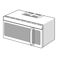
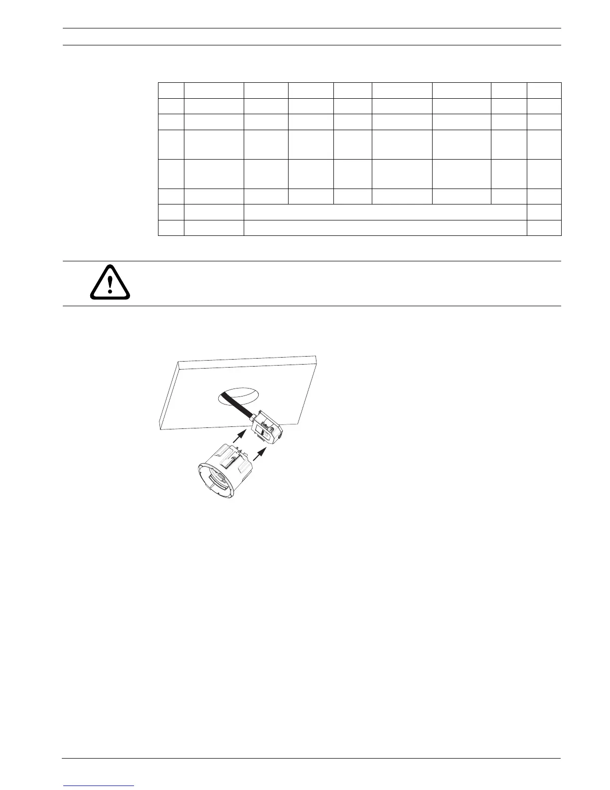
4.7 Attach Housing to the Interface Box
The In-Ceiling Housing is attached to the Interface Box and secured by two (2) thumbscrews.
Figure 4.9 Attach Housing to Interface Box
1. Insert the In-ceiling housing through the hole in the ceiling to verify that the edge of the
hole support the unit. Then remove the housing from the hole.
2. Align the ball studs of the In-Ceiling Housing to the Stud Retainers on Interface Box and
attach.
No. Connector Pin 1 Pin 2 Pin 3 Pin 4 Pin 5 Pin 6 Pin 7
P103 Alarms In Alarm 3 Alarm 4 Alarm 5 Alarm 6 Alarm 7 AGND
P102 Alarms Out Alarm 1 Alarm 2 Alarm 3 GND
P104 Analog Relay Relay
N.O.
Relay
COM
Relay
N.C.
Earth Alarm 1 Alarm 2 Groun
d
P105 Data In/Out C-
(BiPhase)
C+
(BiPhase)
Earth
Ground
RXD (+)
(RS-232/485)
TXD (-)
(RS-232/485)
Signal
Ground
P101 24 VAC Line Earth Neutral
J102 Video BNC Connector Input
J101 UTP/Ethernet Connector Input
WARNING!
24 VAC Class 2 power supply only.
 Loading...