VG4 Modular Camera Series Alarms and Relay Connections | en 99
Bosch Security Systems, Inc. Installation Manual F.01U.216.010 | 8.0 | 2011.02
3. From the AutoDome main menu, select Alarms Setup>Inputs Setup, and set the Alarm
Input # to N.O.S. See the table below for contact and condition details.
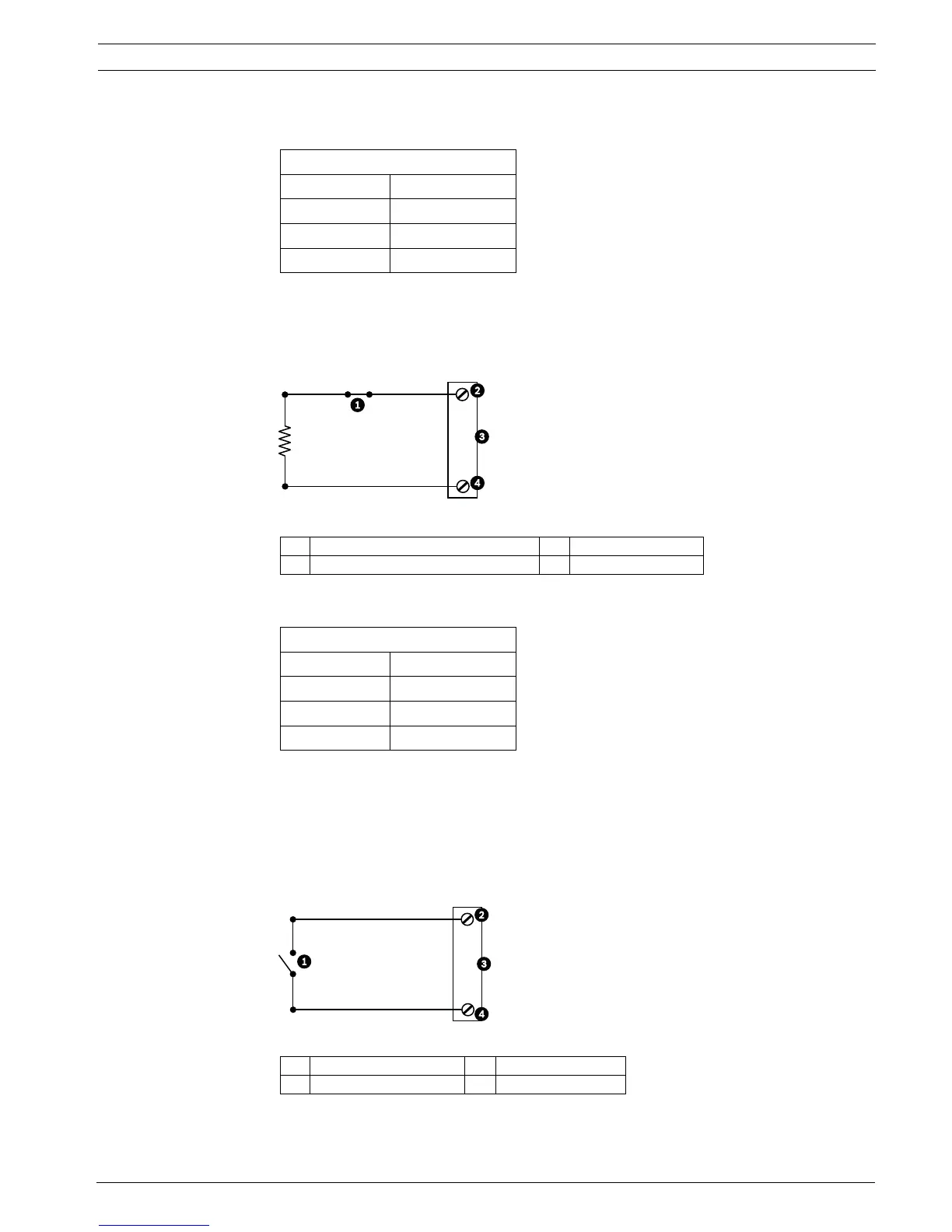
6.2.2 Configuring a Normally Closed Supervised Alarm
1. Install a 2.2 K end-of-line resistor in the alarm circuit.
2. Connect the alarm wires to input 1 or 2 (pin 5 or 6) and to the ground (pin 7) at the
AutoDome.
Figure 6.2 N.C.S. - Normally Closed Supervised Connections
3. From the AutoDome main menu select Alarm Setup>Inputs Setup, and set Alarm Input #
to N.C.S. See the table below for contact and condition details.
6.3 Configuring Non-supervised Alarms (inputs 1 through 7)
You can configure alarms 3 through 7 as non-supervised Normally Open (N.O.) or Normally
Closed (N.C.) alarms.
6.3.1 Configuring a Normally Open Non-supervised Alarm
1. Connect the alarm to the appropriate input (1 through 7) and ground at the AutoDome.
Figure 6.3 N.O. - Normally Open Non-supervised Connections
AutoDome Programmed N.O.S.
Contact Alarm Condition
Open Normal
Closed Alarm
Cut or brake Tamper
1 Dry Contact 3 Dome Connector
2 Alarm 1 or 2 only (Pin 5 or 6) 4 Ground (Pin 7)
AutoDome Programmed N.C.S.
Contact Alarm Condition
Open Alarm
Closed Normal
Short Tamper
1 Dry Contact 3 Dome Connector
2 Alarm Inputs 1 to 7 4 Ground
 Loading...