VG4 Modular Camera Series Installing Roof Parapet and Pipe Mounts | en 51
Bosch Security Systems, Inc. Installation Manual F.01U.216.010 | 8.0 | 2011.02
– The second method is to bypass the Power Supply Box and route the video, control, and
alarm wires directly to the Interface Board. You connect only the power wires inside the
Power Supply Box.
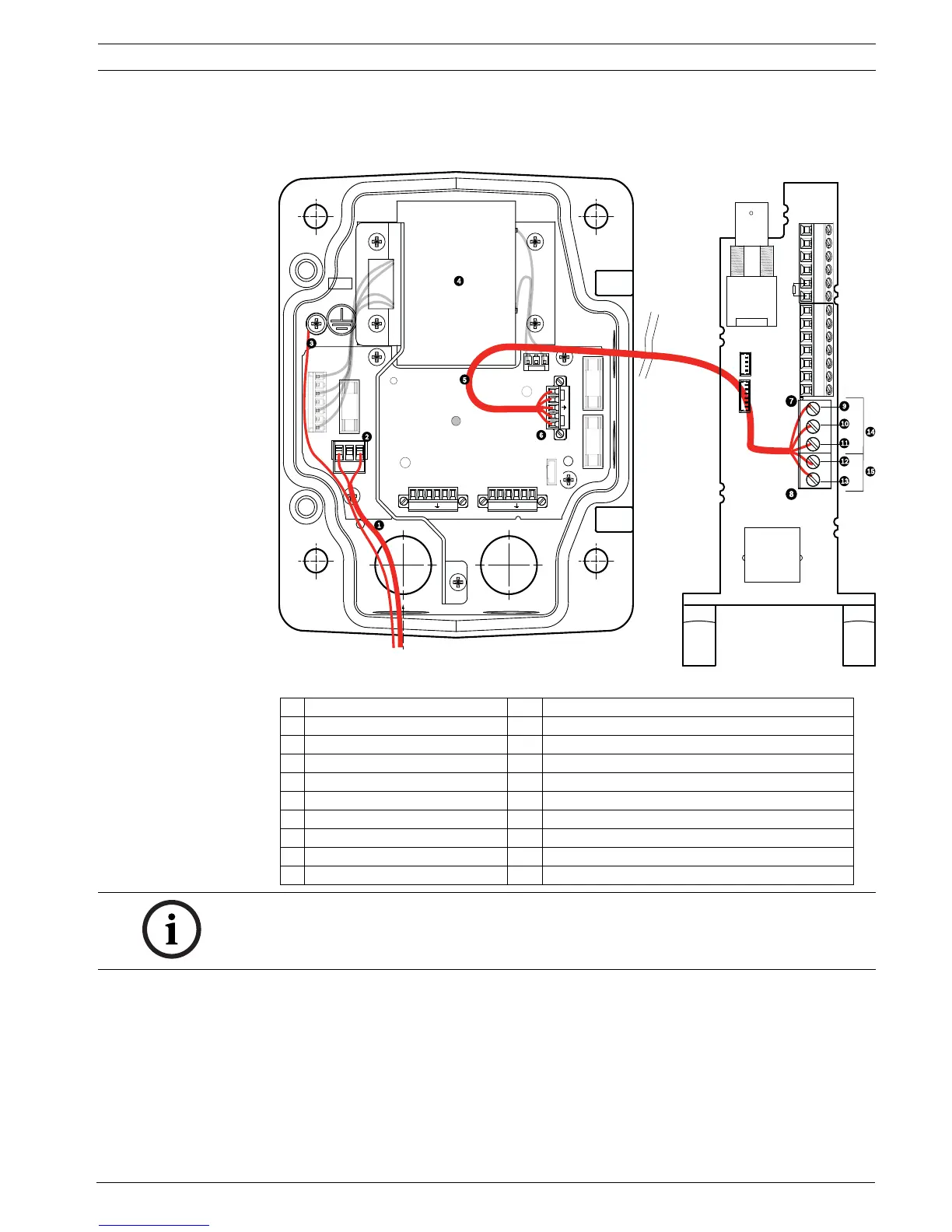
Figure 3.4 VG4-A-PSU1 or VG4-A-PSU2 Power Supply Box Connected to Pipe Interface Board
VG4-A-PSU1/VG4-A-PSU2 Pipe Interface Board
1 120 VAC/230 VAC Power In 7 P101 Connector
2 P101 Connector 8 P107 Connector
3 Ground Connection 9 24 VAC Power In (to AutoDome)
4 Transformer 10 Earth Ground
5 24 VAC Power Out 11 24 VAC Power In (to AutoDome)
6 P107 Connector 12 24 VAC Power In (to Heater)
13 24 VAC Power In (to Heater)
14 AutoDome Power
15 Heater Power
GND TXD RXD C+ C-GND TXD RXD C+ C-
P101
P106 P105
P107
XF102 XF103
XF101
5 4 3 2 1
1
2
J101
(LED)
HTR DOME
24V NC 24V
FUSE
FUSE
FUSE
BNC
J102
P107 P101
P102
P103
P104
P106
J101
AGND
A7
A6
A5
A4
A3
AGND
OUT 3
OUT 2
OUT 1
P105
NOTICE! Fiber Optic Models require that the Biphase control wires be routed from the Power
Supply Box P106 connector out to the Pipe Interface Board P105 connector.
 Loading...