VG4 Modular Camera Series Installing Roof Parapet and Pipe Mounts | en 53
Bosch Security Systems, Inc. Installation Manual F.01U.216.010 | 8.0 | 2011.02
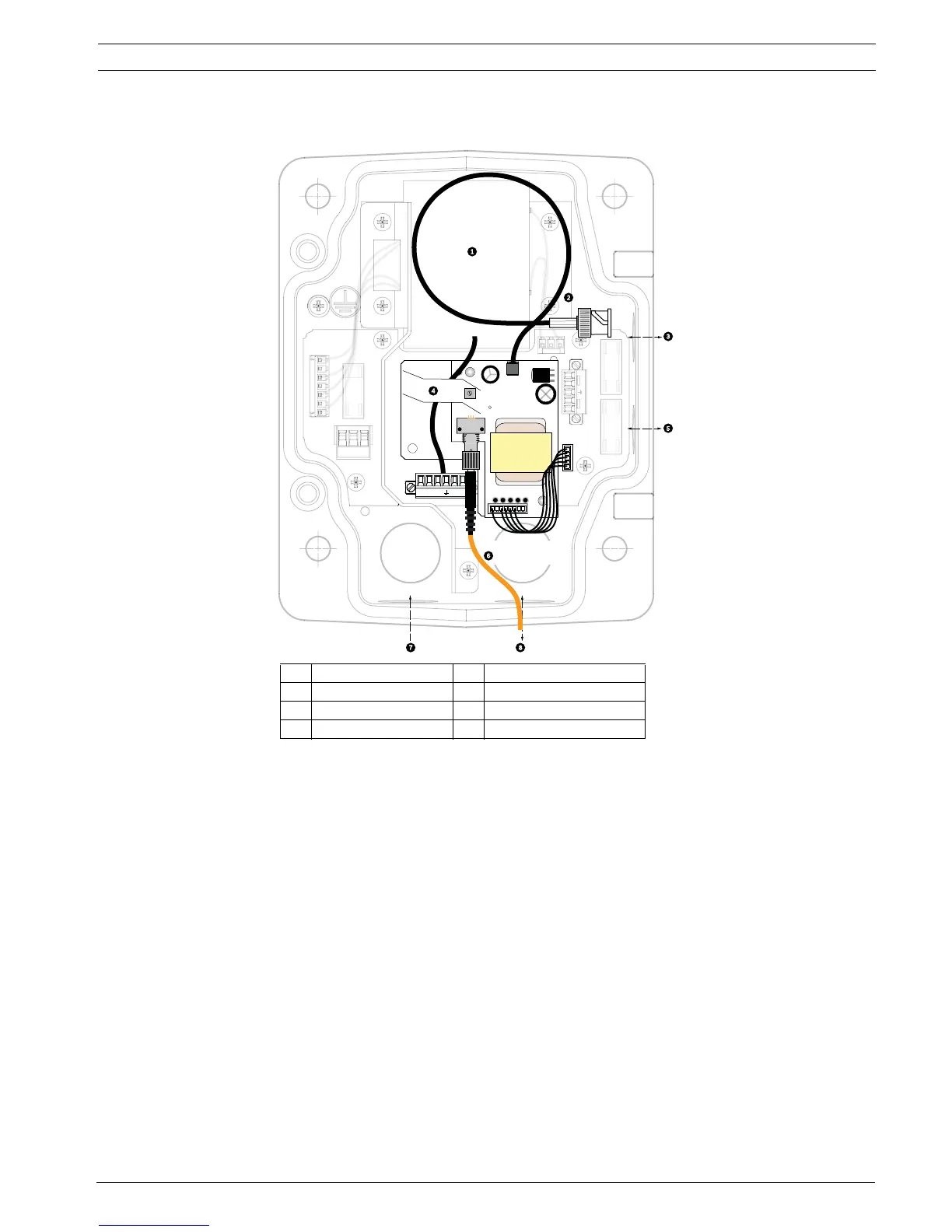
3. Route the control wires from the Power Supply to the Pipe Interface Board. Then attach
the supplied six (6) pin control data connector to the wires in the Power Supply Box.
1 Transformer 5 In/Out
2 BNC to Dome 6 ST Connector (Fiber)
3In/Out 7Power In
4 From Arm Harness 8 Data In/Out
(GND)
FUSE)
FUSE)
FUSE
24V N
24V
 Loading...