92 en | Cable and Wire Standards VG4 Modular Camera Series
F.01U.216.010 | 8.0 | 2011.02 Installation Manual Bosch Security Systems, Inc.
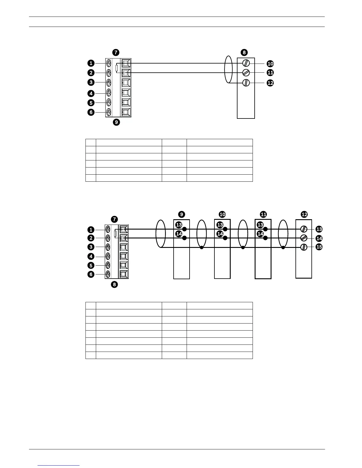
The figure below illustrates the connections necessary for Biphase operation.
Figure 5.2 Connections for Biphase Operation
In a daisy chain configuration, where multiple domes are connected in series, the 100 ?
resistor must be removed from all but the last dome. You can daisy chain a maximum of four
(4) AutoDomes.
Figure 5.3 Connections for a Daisy Chain Configuration
1 C- (Biphase) 7 AutoDome Data In/Out
2 C+ (Biphase) 8 Head End Biphase
3 Earth Ground 9 P105/P106 Connector
4 RxD 10 C- (Biphase)
5 TxD 11 C+ (Biphase)
6 Signal Ground 12 Shield
1 C- (Biphase) 9 Dome 3
2 C+ (Biphase) 10 Dome 2
3 Earth Ground 11 Dome 1
4 RxD 12 Head End Biphase
5 TxD 13 C- (Biphase)
6 Signal Ground 14 C + (Biphase)
7 Last Dome Data In/Out 15 Shield
8 P105/P106 Connector
100 Ω
 Loading...