96 en | Cable and Wire Standards VG4 Modular Camera Series
F.01U.216.010 | 8.0 | 2011.02 Installation Manual Bosch Security Systems, Inc.
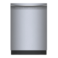
7. Connect the green (RxD) wire to the C+ pin on the P106 connector.
Figure 5.8 Detail of P106 Connections
8. Connect the fiber optic cable from the AutoDome to the LTC 4629.
9. Close the door to the power supply unit.
10. Ensure that the VG4 AutoDome is set to receive RS232 commands.
– Remove the bubble from the VG4 AutoDome housing.
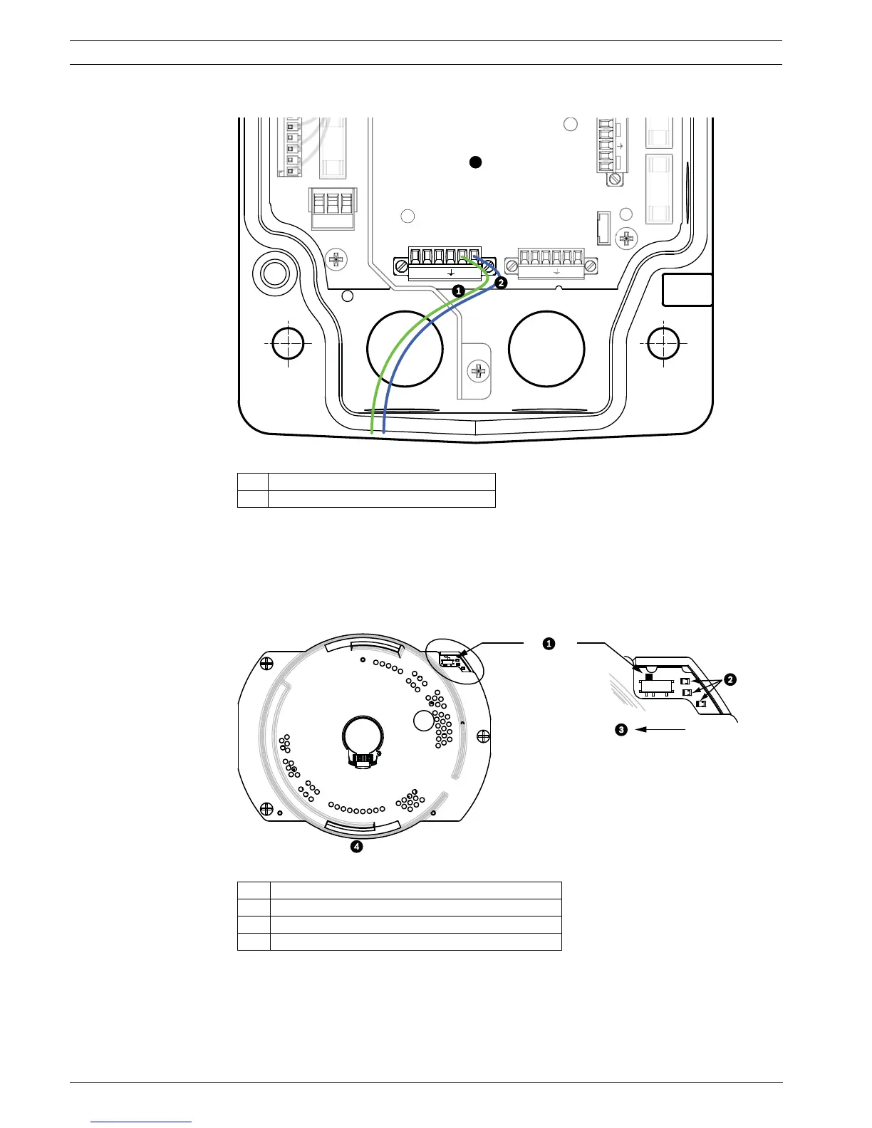
– Locate the protocol switch on the CPU board.
– Ensure that the protocol switch is in the left position for RS232 operation.
Figure 5.9 Position of CPU Switch for RS232 Operation
11. Return the bubble to the AutoDome housing.
12. Return power to the power supply box.
1 Green RxD wire connected to C+
2 Blue Ground wire connected to C-
1 Switch Location
2LEDs
3 Move Switch to the left for RS232 Operation
4CPU Module
+
-
24 VA
P
P1
7
F1
2
XF1
1
5 4
LED
4V NC 24V
 Loading...