22 MU 100 – 6721804146 (2019/10)
Caption to the figure above and connection diagrams with
system schematics at end of document:
Protective conductor
Connecting terminal designations:
230 V AC Mains voltage connection
BUS BUS system connection
BMS Building Management System with 0-10 V
interface
HS Heat Source on BUS system
OE1-74 Mains voltage output, solenoid valve
OE1-75 Fault output (230 V)
PC0 Mains voltage output, pump (230 V)
IE0 Pump alarm output
(default setting: N/O contact)
OP0 Pump on/off (output/potential-free contact
≤ 24 V), coding position 3‒5: potential-free
fault output
T0 Low loss header temperature sensor input
1)
IO1-1(+),2(-) Feedback output for heat source power
(0-10 V)
IO1-3(+),4(-) Input for heat source activation
(setpoint value 0–10 V)
OC0 1-2 Output for pump control signal
(setpoint value 0-10 V/PWM)
2)
OC0 1-3 Pump feedback input (pulse width modulation),
optional
2)
CON Control unit with BUS system (Controller)
MC Boiler control device (Master Controller)
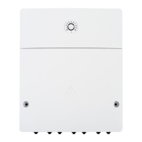
MM 100 Heating circuit module (EMS/EMS 2/EMS plus)
MU 100 Extension module
T0
NL N N74 N6375L
120/230VAC 120/230VAC
OE1 PC0
1212 12
IE0 OP0
BUS
12
T0
120/230 V AC
≤ 24 V
IO1
IO1
≤ 24 V
213 23
IO1
41
OC0
MU 100
230 V AC
BUS
230 V AC
0-10 V
0-10 V
(+) (–)
12
(+) (–)
34
OE1 OE1
L
N
PC0
NL
M
OP0IE0
3
21
OC0
OC0
PWM
123
OC0
0-10V
123
0010028622-001
1) The heat exchanger sensor is T0 with the heat exchanger.
2) Observe coding switch position.
 Loading...


