-26-
Adjustments
45° Bevel Stop
Checking 45° Bevel Stop Setting
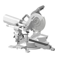
1. Hold the saw head assembly (Fig. 22, 28) down and
push in the head assembly lock pin (8) to keep the saw
in the DOWN position.
2. Slide the saw head assembly (28) completely to the back
and tighten the slide rail lock knob (7).
3. Rotate the table to the 0° miter position.
4. Rotate the bevel lock knob (Fig. 20, 34) clockwise to un-
lock the head assembly.
5. Move the left sliding fence (Fig. 22, 12) fully to the left.
6. Check the position of the bevel stop indicator (Fig. 24,
33). It should be at the “45°” position.
7. Tilt the saw head assembly (Fig. 22, 28) to the left (coun-
terclockwise) until it hits the 45° stop. This is where the
saw’s 45° stop is set to make a 45° left bevel cut.
8. Use a combination square to check that the blade is 45°
to the table. Remove the rule blade from the combination
square (Fig. 25). Place only the combination square’s
head on the saw’s table with its long flat side resting on
the table and its 45° side against the tilted blade (25).
8
22
28
12
7
Fig. 22
0° Bevel
Adjustment
Screw
Fig. 23
Fig. 24
33
Lock nut
Bevel stop bolt
Fig. 25
Combination
square
25
Square’s
45° side
 Loading...