Installation 29/60
RE 92714-01-B/04.2018, A10VO, A10VSO, A10VSNO Series 32, Bosch Rexroth AG
If the minimum fluid level is equal to or below the upper edge of the pump, see
chapter 7.3.3 “Above-reservoir installation” on page 30.
Axial piston units with electric components (e.g., electric controls, sensors) must
not be installed in a reservoir below the fluid level.
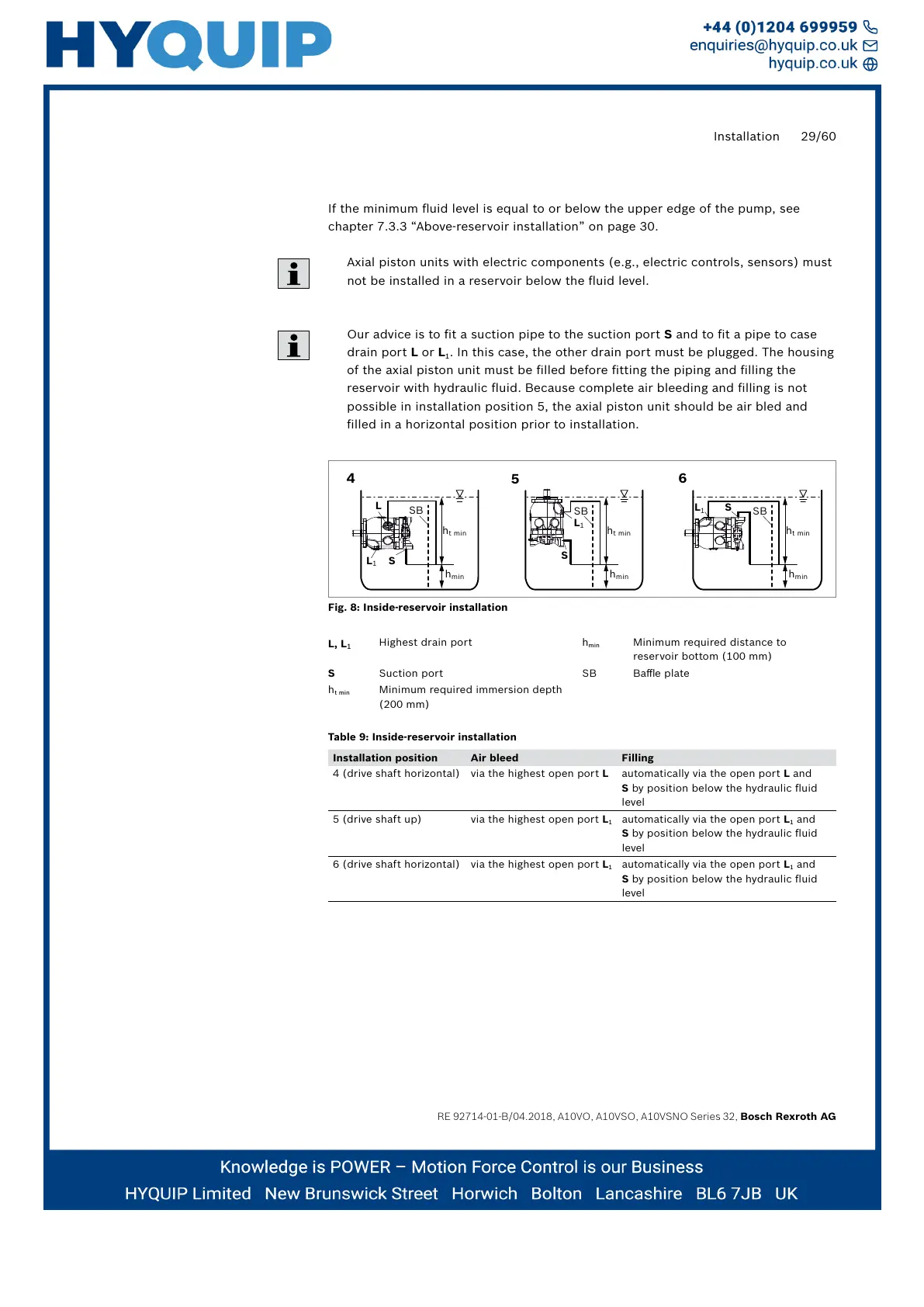
Our advice is to fit a suction pipe to the suction portS and to fit a pipe to case
drain port L or L
1
. In this case, the other drain port must be plugged. The housing
of the axial piston unit must be filled before fitting the piping and filling the
reservoir with hydraulic fluid. Because complete air bleeding and filling is not
possible in installation position 5, the axial piston unit should be air bled and
filled in a horizontal position prior to installation.
4
5
6
L
L
1
S
L
1
S
h
min
h
t min
SB
h
min
h
t min
SB
h
min
h
t min
SL
1
SB
Fig. 8: Inside-reservoir installation
L, L
1
Highest drain port h
min
Minimum required distance to
reservoir bottom (100 mm)
S Suction port SB Baffle plate
h
t min
Minimum required immersion depth
(200 mm)
Table 9: Inside-reservoir installation
Installation position Air bleed Filling
4 (drive shaft horizontal) via the highest open port L automatically via the open port L and
S by position below the hydraulic fluid
level
5 (drive shaft up) via the highest open port L
1
automatically via the open port L
1
and
S by position below the hydraulic fluid
level
6 (drive shaft horizontal) via the highest open port L
1
automatically via the open port L
1
and
S by position below the hydraulic fluid
level