28/60 Installation
Bosch Rexroth AG, A10VO, A10VSO, A10VSNO Series 32, RE 92714-01-B/04.2018
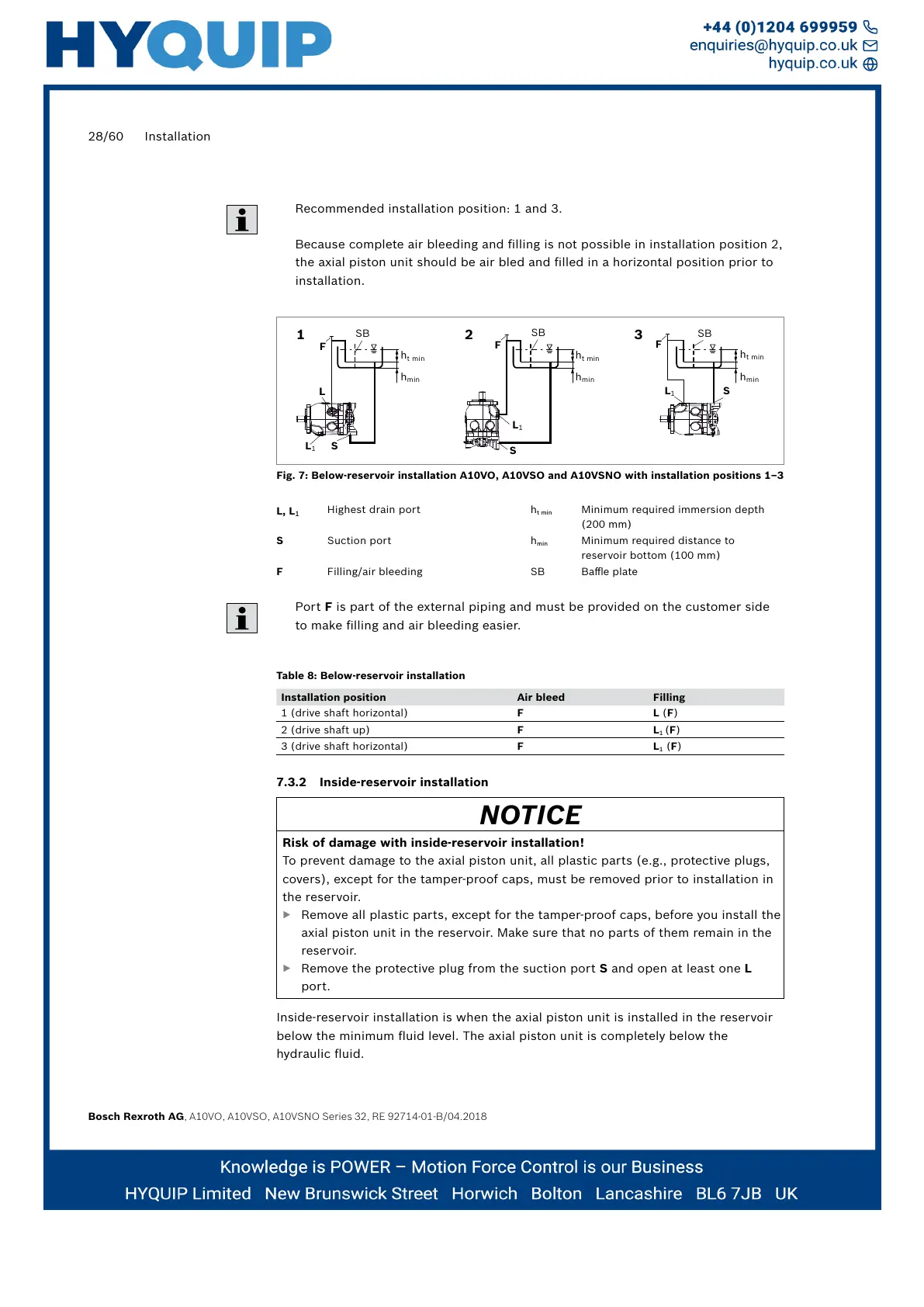
Recommended installation position: 1 and 3.
Because complete air bleeding and filling is not possible in installation position 2,
the axial piston unit should be air bled and filled in a horizontal position prior to
installation.
1 2 3
SB
L
L
1
L
S
h
t min
h
min
L
1
S
h
t min
h
min
SB
L
1
S
h
t min
h
min
F
SB
F
F
Fig. 7: Below-reservoir installation A10VO, A10VSO and A10VSNO with installation positions 1–3
L, L
1
Highest drain port h
t min
Minimum required immersion depth
(200 mm)
S Suction port h
min
Minimum required distance to
reservoir bottom (100 mm)
F Filling/air bleeding SB Baffle plate
Port F is part of the external piping and must be provided on the customer side
to make filling and air bleeding easier.
Table 8: Below-reservoir installation
Installation position Air bleed Filling
1 (drive shaft horizontal) F L (F)
2 (drive shaft up) F L
1
(F)
3 (drive shaft horizontal) F L
1
(F)
7.3.2 Inside-reservoir installation
NOTICE
Risk of damage with inside-reservoir installation!
To prevent damage to the axial piston unit, all plastic parts (e.g., protective plugs,
covers), except for the tamper-proof caps, must be removed prior to installation in
the reservoir.
▶ Remove all plastic parts, except for the tamper-proof caps, before you install the
axial piston unit in the reservoir. Make sure that no parts of them remain in the
reservoir.
▶ Remove the protective plug from the suction port S and open at least one L
port.
Inside-reservoir installation is when the axial piston unit is installed in the reservoir
below the minimum fluid level. The axial piston unit is completely below the
hydraulic fluid.