3 609 929 B37/2008-09 | IM24V Bosch Rexroth AG 21/84
ENGLISH
ENGLISH
ITALIANO
ESPAÑOL
PORTUGUÊS
SVENSKA
FRANÇAIS
4 Product description
X1S1 interface
This interface is designed as a two-pin
spring-type terminal to connect an external
24 V power supply.
Fig. 2: Two-pin spring-type terminal (female)
XDD1 interface
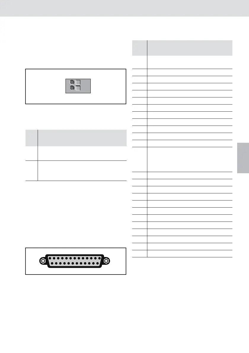
This interface is designed as a 25-pin SUB-D
plug connector for digital inputs/outputs. The
logical assignment of the internal tightening
system signals to the respective inputs/
outputs is done with the BS350 operating
system.
Fig. 3: 25-pin SUB-D plug connector (female)
Table 1 X1S1
Pin Signal Description/
function
Voltage/
current
1 24 V 24 V external
supply voltage
24 V, 3 A
2 0V Reference
potential for
external 24 V
2
1
24V
GND
113
1425
Table 2 XDD1
Pin Signal Description/
Function
Voltage/
current
1 24 V 24 V external
supply voltage
24 V, 3 A
2 I2 Input 2 24 V
3 I4 Input 4 24 V
4 I6 Input 6 24 V
5 I8 Input 8 24 V
6 I10 Input 10 24 V
7 O2 Output 2 24 V/500 mA
8 O4 Output 4 24 V/500 mA
9 O6 Output 6 24 V/500 mA
10 O8 Output 8 24 V/500 mA
11 O10 Output 10 24 V/500 mA
12 O12 Output 12 24 V/500 mA
13 0V Reference
potential for
24 V
external
14 I1 Input 1 24 V
15 I3 Input 3 24 V
16 I5 Input 5 24 V
17 I7 Input 7 24 V
18 I9 Input 9 24 V
19 O1 Output 1 24 V/500 mA
20 O3 Output 3 24 V/500 mA
21 O5 Output 5 24 V/500 mA
22 O7 Output 7 24 V/500 mA
23 O9 Output 9 24 V/500 mA
24 O11 Output 11 24 V/500 mA
25 O13 Output 13 24 V/500 mA
IM24V.book Seite 21 Donnerstag, 25. September 2008 1:13 13
 Loading...


