22/84 Bosch Rexroth AG IM24V | 3 609 929 B37/2008-09
4 Product description
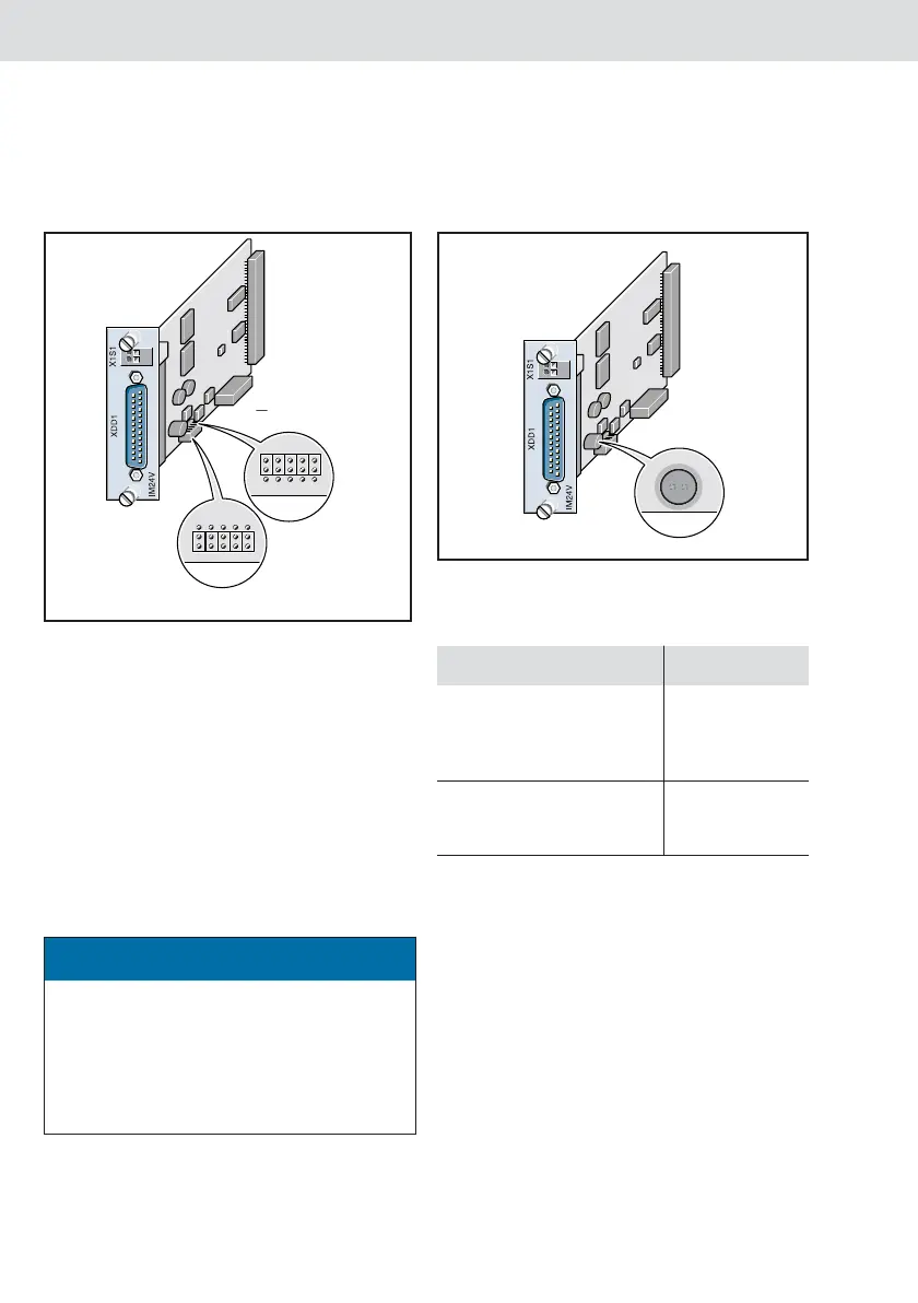
Jumper
The jumper on the circuit board makes it
possible to select between an internal and
external power supply for the outputs.
Fig. 4: IM24V, side view, jumper assignment for
internal/external power supply
1)
Factory setting
The internal power supply is used if “Internal”
is selected. The total current for the outputs
may not exceed max. 1 A.
The external power supply, which must be
connected at the X1S1 or XDD1 interface, is
used if “External” is selected. The total
current for the outputs may not exceed max.
3 A (protected via a fuse).
Fuse
The maximum permissible current is limited to
3.15 A via the UL fuse if an external power
supply is used.
Fig. 5: Fuse
ATTENTION
The voltage circuits on the terminal are
safely isolated from the mains circuits (safe
isolation in accordance with EN50178).
The requirements for safe isolation of
electric circuits must be observed if using
the connection options on this terminal.
Extern
Intern
24V extern
1)
4V
GND
External
Internal
Table 3
Microfuse type Supplier
TR 5, no. 372; 3.15 A
delayed;
spacing 5.08 mm,
pin length 4.3 mm
Wickmann
MSTU 250, 3.15 A delayed;
spacing 5.08 mm,
pin length 4.3 mm
Schurter
4V
GND
IM24V.book Seite 22 Donnerstag, 25. September 2008 1:13 13