4 Technical Data
4.1 Equipment
Processor STMicroelectronics ST40with at least 192 MHz
Random access memory
(RAM)
At least 32 Mbytes DRAM and at least 32 Kbytes
NvRAM
Interfaces:
Interface to I/O modules
Communication interface
Rexroth Inline interface
1 x Ethernet connection (RJ 45, 10/100 Base-T)
Inputs and outputs 8 electrically isolated digital inputs
4 electrically isolated digital outputs
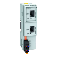
Fig.4-1: Equipment
4.2 Power Supply
The IndraControl L10 is supplied with 24 V. The following values of the oper‐
ating voltage comply with DIN EN 61131-2:
Nominal value
24 VDC
Tolerances -15 % / +20 % (without residual ripple)
Residual ripple +/-5 %
Umax 30 V
Umin 19.2 V
Fig.4-2: Operating voltage according to DIN EN 61131-2
Three operating voltages can be applied on the IndraControl L10 (refer to
chapter 7.2.1 "External Supply Voltages" on page 24). Current consumption
from these voltages is as follows:
Current consumption by U
LS
1.25 A max
Current consumption from U
M
and
U
S
Max. of 8 A in total
Fig.4-3: Current consumption
The power consumption of the IndraControl L10
(no I/O connected)
is normally 4.6 watt.
4.3 Ambient Conditions
In operation Storage / Transport
Max. ambient temperature +5 ... +55 °C -25 °C bis +70 °C
Relative humidity RH-2; 5 % to 95 % acc. to
DIN EN 61131-2,
Condensation not al‐
lowed.
Project Planning Manual | Rexroth IndraControl L10 Electric Drives
and Controls
| Bosch Rexroth AG 15/54
Technical Data
Courtesy of CMA/Flodyne/Hydradyne ▪ Motion Control ▪ Hydraulic ▪ Pneumatic ▪ Electrical ▪ Mechanical ▪ (800) 426-5480 ▪ www.cmafh.com

 Loading...


