When the dynamization outputs do not work, check the power
supply connection. The polarity might
possibly have been
reversed.
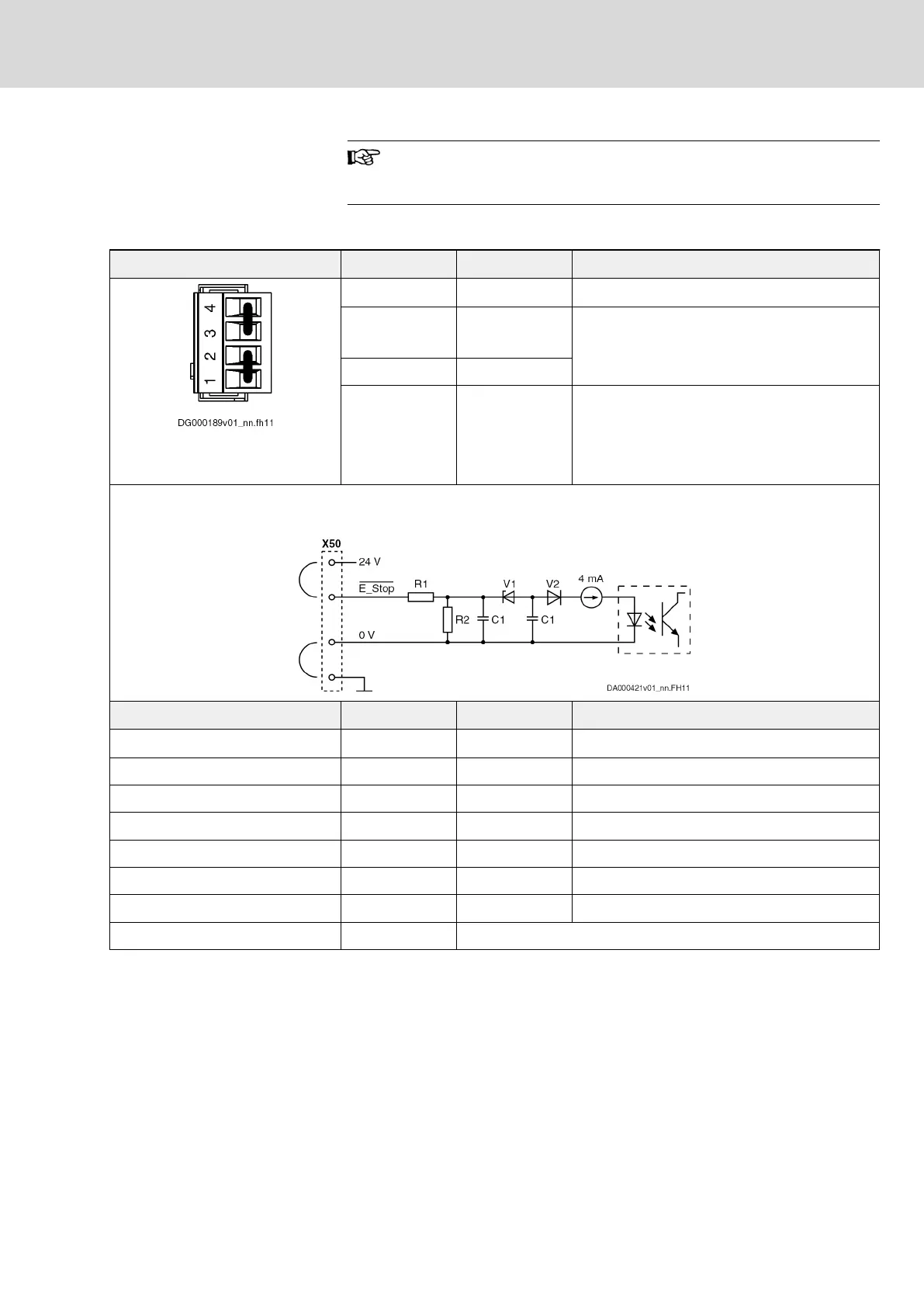
X50, E-Stop Input
View Connection Signal name Function
Condition as supplied:
With jumpers at 1-2 and 3-4
4 24V
24V output for E-Stop input
1)
3 ______
E-Stop
Digital input for E-Stop
(isolated; active with input voltage "L")
2 0V
1 0V
0V output for E-Stop input
2)
The input complies with EN61131-2, type 1.
Input circuit (R1 = approx. 1k; R2 = approx. 7k4; C1 = approx. 10 nF; V1 = approx. 6 V; V2 = approx. 0.7 V):
Spring terminal (connector) Unit Min. Max.
Connection cable stranded wire
mm
2
0,5 1,5
Connection cable AWG 20 16
Allowed input voltage V -3 30
Input voltage "H" V 15 30
Input current "H" mA 2 15
Input voltage "L" V 0 5
Input current "L" mA 0 > 0,5
Input resistance kΩ 2,5
1) Exclusively use the 24 V output for the E-Stop input in conjunc‐
tion with the jumper from X50.3 to X50.4. Maximum power rat‐
ing: 15 mA.
2) Exclusively use the 0 V output for the E-Stop input in conjunc‐
tion with the jumper from X50.1 to X50.2. Maximum rating:
15 mA.
Tab. 12-7: Function, Pin Assignment, Properties
See also description of the E-Stop function: chapter 12.3.5 "E-Stop function"
on page 137
DOK-INDRV*-SI3-**VRS**-AP06-EN-P
Rexroth IndraDrive Integrated Safety Technology "Safe Torque Off" (as of MPx-16)
Bosch Rexroth AG 125/149
Project planning
LSA Control S.L. www.lsa-control.com comercial@lsa-control.com (+34) 960 62 43 01