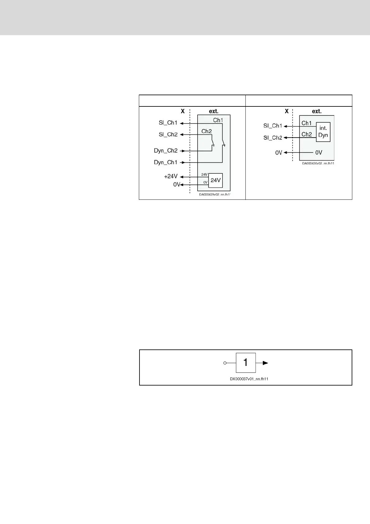
● Passive safety unit with internal
dynamization pulses in conjunction with
external safety technology contacts and an external 24V power supply
unit
● Active safety unit via a safety PLC
Passive safety unit Active safety unit
int. Dyn: Dynamization pulses are
internally generated
ext. External safety unit for a safety zone
X Connection point of the safety zone beginner
Tab. 12-21: Signal input
Safety zone node
When a KSM/KMS with optional safety technology is to be a safety zone
node within a safety zone, X141 must be equipped with the connector
RBS0023.
KSM/KMS without optional safety technology do not require the connector,
because for these devices the signals are directly transmitted to the next
safety zone node via X103.1 and X103.2. KSM/KMS without optional safety
technology are not safety zone nodes and do not react to safety technology
signals.
12.4 Technical data of inputs and outputs
12.4.1 Digital inputs (safety technology L options)
The digital inputs correspond to IEC 61131, type 2.
Fig. 12-12: Symbol
DOK-INDRV*-SI3-**VRS**-AP06-EN-P
Rexroth IndraDrive Integrated Safety Technology "Safe Torque Off" (as of MPx-16)
Bosch Rexroth AG 141/149
Project planning
LSA Control S.L. www.lsa-control.com comercial@lsa-control.com (+34) 960 62 43 01