● When a KSM02/KMS02 device has
been configured as a safety zone
beginner (X141.3 = n. c., P-0-0249 = 2) and no E-Stop signal has been
assigned to this KSM02/KMS02, the E-Stop signal of the preceding
safety zone is transmitted.
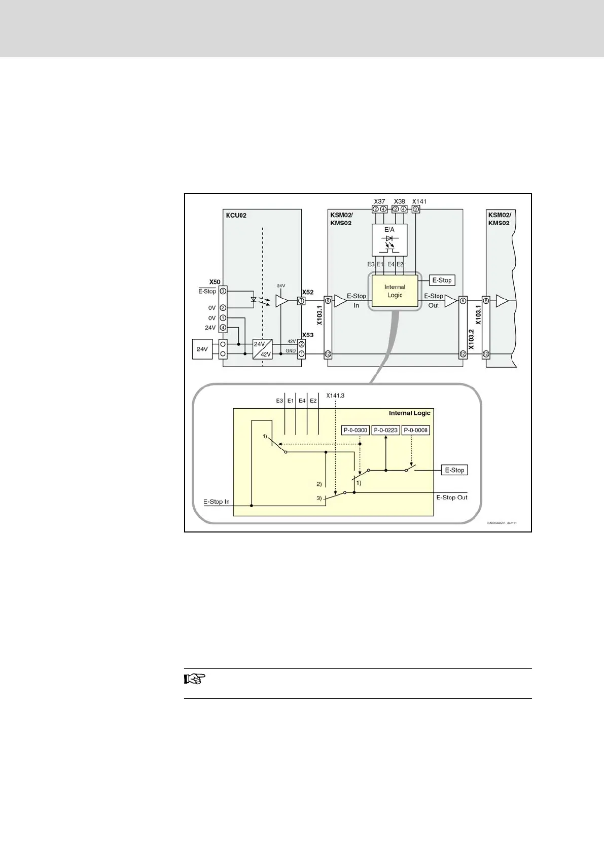
In this case, the E-Stop signal is input to the safety zone via an isolated
24V contact (X50.3) at KCU02. The reference potential of the E-Stop
signal within the safety zone is X53.1 (output of the DC-DC converter in
KCU02).
E1, E2, E3, E4 Digital inputs
P-0-0300 Digital inputs, assignment list
P-0-0223 E-Stop input
P-0-0008 Activation E-Stop function
1) Switch position when P-0-0223 (E-Stop input) not entered in
any element of P-0-0300 (default state)
2) Switch position when X141 equipped with cable RKB0033 or
open; P-0-0249 = 2 (zone beginner)
3) Switch position when X141 equipped with connector
RBS0023; P-0-0249 = 1 (zone node)
Fig. 12-8: E‑Stop zone setup
The E-Stop zone setup is independent of whether a safety
technology option L3 is available or not.
Bosch Rexroth AG DOK-INDRV*-SI3-**VRS**-AP06-EN-P
Rexroth IndraDrive Integrated Safety Technology "Safe Torque Off" (as of MPx-16)
138/149
Project planning
LSA Control S.L. www.lsa-control.com comercial@lsa-control.com (+34) 960 62 43 01