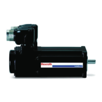
4.2.2 Mechanical interfaces
Type A
☐ Flange
[mm]
B
Length
[mm]
C
Shaft Ø
[mm]
D
Shaft length
[mm]
E
Centering
collar [mm]
F
Hole circle
[mm]
G
Mounting
hole [mm]
MS2N03-B
58
See specifi-
cations
1)
9 20
40 63 4.5
MS2N03-D 11 23
MS2N04 82 14 30 50 95 6.6
MS2N05 98 19 40 95 115 9
MS2N06 116 24 50 95 130 9
MS2N07 140 32 58 130 165 11
MS2N10 196 38 80 180 215 14
Tab. 4-2: Mechanical interface flange, shaft
Use the following screws
2)
and washers for flange fastening.
Screw M4 M6 M8 M10 M12 M14
Mounting holes ⌀ [mm] 4.5 6.6 9 11 14 18
Tightening torque M
A
[Nm] at μ
K
= 0.12
3.0 10.1 24.6 48 84 206
Washer DIN EN ISO 28738 - - Yes Yes Yes Yes
Tab. 4-3: Tightening torque of mounting screws
1)
Additional documentation DOK-MOTOR*-MS2N*******-PRIX-EN-P, Project planning manual
2)
Screws according to DIN EN ISO 4762 or DIN EN ISO 4014. Fastening class 8.8. The screw
lengths depends on material and installation situation. The specified tightening torque must
be ensured.
MS2N Synchronous Motors Bosch Rexroth AG
About this product
DOK-MOTOR*-MS2N*******-IT03-EN-P
11/95

 Loading...


