● High performance data
● High dynamics (owing to the favorable ratio of torque to inertia mass)
● High overload capability (owing to the favorable heat dissipation from the
stator windings to the outside wall of the motor housing)
● Peak torque utilizable across a wide speed range (owing to electronic
commutation)
● Continuous start-stop operation possible with high repeat frequencies
(owing to electrical commutation)
● Easy attachment to the machine (owing to flange according to DIN 42948)
11.65)
● Any installation position
● Simple and fast startup (thanks to data memory)
Structure and components
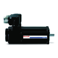
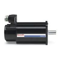
MKE motors are permanent-magnet motors with electronic commutation. Spe‐
cial magnet materials permit the motors to be designed with low inertia masses.
The following figure shows the principal design of MKD motors.
(1) Drive shaft
(2) Stator with winding
(3) Bearings
(4) Motor encoder
(5) Connection unit
(6) Terminal box lid
(7) Holding brake (optional)
(8) Grounding clamp
(9) Shaft sealing ring
(10) Rotor with permanent magnets
Fig.1-2: Design of MKE motors
1.1.2 Versions
MHE motors are available in various designs. On the basis of existing national
regulations and standards, the MKE motors have to be subdivided into housing
types
● E according to European Standard (EU) and
● U according to American Standard (UL)
.
8/131 Bosch Rexroth AG | Electric Drives
and Controls
Rexroth MKE Synchronous Motors | Project Planning Manual
Introduction to the Product

 Loading...


