● When placing the home position circuit breaker and during the reference,
note that the resolver's mode of action generates several reset signals
during a mechanical motor revolution.
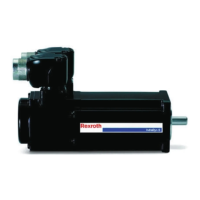
● For MKE037 and MKE047: 3 reset signals per revolution
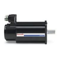
● For MKE098: 4 reset signals per revolution
● Avoid too high a gear ratio or to slight a feed-constant.
Resolver feedback (RSF) with inte‐
grated multiturn absolute encoder
Provided for absolute indirect position detection within 4096 motor revolutions.
Replaces separate absolute value encoders on the motor.
The absolute axis position for this encoder variant remains valid
after power shut down because of the battery back-up. The nominal
durability of the batterie is about 10 years.
Digital servo feedback (HSF)
Provided for relative indirect position detection. Replaces separate incremental
encoder on the motor.
After a voltage failure or after the first POWER ON, the axis must
first always be moved to its home position.
Digital servo feedback (HSF) with
integrated multiturn absolute en‐
coder
Provided for absolute indirect position detection within 4096 motor revolutions.
Replaces separate absolute encoder on the motor.
The absolute axis position for this encoder variant remains valid
after power shut down because of the battery back-up.
Optical singleturn encoder
Option A, B
These encoders permit absolute, indirect position recording within one me‐
chanical rotation. The encoders replace separate incremental encoders on the
motor.
After a power failure or after the first POWER ON, the axis must first
always be moved to its home position.
Exception: Applications in which the maximum working path is with‐
in one mechanical rotation of the motor.
Multiturn absolute optical encoder
Option C, D
These encoders permit absolute, indirect position recording within 4096 me‐
chanical rotations. The encoders replace a separate absolute value encoder
on the motor. With this encoder version, the absolute position of the axis is
preserved even after voltage switch-off.
7.2 Holding Brakes
The holding brake serves to hold the axis when the machine is in a de-energized
state. In normal operation, use the holding brake only at standstill or for EMER‐
GENCY STOP in order to deactivate an axis (n < 10 min
-1
).
Please observe the application notes when using holding brakes in chapter
9.11 "Holding Brakes (Ex)" on page 90.
For technical data and availability of holding brakes, see chapters
"Technical data" and "Type codes".
62/131 Bosch Rexroth AG | Electric Drives
and Controls
Rexroth MKE Synchronous Motors | Project Planning Manual
Options and Accessories

 Loading...


