on the motor flange). Protective conductor cross-section see fig. 8-2 " Additional
protective conductor" on page 66.
8.3 Connection according to American Standard (UL)
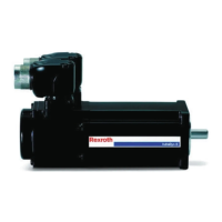
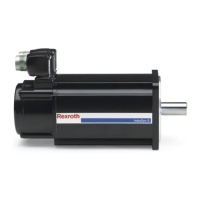
Fig.8-5: Connection overview according to American standard
The connection of the MKE motors, according to American standard, consists
of the following components:
● a power connector, incl. connection for temperature sensor and holding
brake, single-wire construction
● encoder connection, standard-cable construction
● additional outside connection for an equipotential bonding conductor (ac‐
cording to EN 50014: 1992)
Power and encoder connection
The connection cable of the MKE motors are to be realised through a special
cable duct into the motor. The ca. 1.5 m long connection cables have to be led
through a ¾ inch metal pipe into an approved Ex terminal box (see fig. 8-1 "
Connection variants MKE motors" on page 65). Standard connection cables
lead from an Ex terminal box to a drive control device.
68/131 Bosch Rexroth AG | Electric Drives
and Controls
Rexroth MKE Synchronous Motors | Project Planning Manual
Connection Technique

 Loading...


